
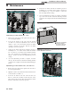
Install Instructions


66
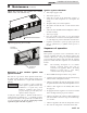
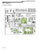
9 Glossary
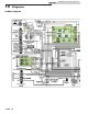
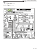
Power Supply
(AC120VAC/60Hz)
120VAC/60Hz/1PH power connects to black (line) and white
(neutral) wires located within an electrical wiring box located
on the left side of the unit. A green chassis grounding wire is
also provided for connection to earth ground.
ON/OFF Rocker Switch
The black line voltage wire runs directly to a single pole, single
throw On/Off rocker switch located behind the front cover
accessible by a thumb screw. Turning ON the rocker switch
delivers line voltage to the low voltage transformer and ignition
module.
Note: The On/Off switch does not provide for disconnection
of power being supplied to any remotely connected
devices that may be connected to the unit (i.e. pumps,
louvers, power venters, etc.,). As such, it may be
necessary to locate and turn off power to these items
before attempting to service the unit.
Low Voltage Supply Transformer
A 120VAC to 24VAC transformer located within the control
panel provides 24VAC/60Hz to many of the components located
on the unit. One of its 24VAC outputs (blue) is connected to a
circuit breaker and the other (yellow) is connected to chassis
ground.
24VAC Circuit Breaker
A circuit breaker is provided on Models 987 - 2067 for protection
of the low voltage supply transformer from overloads and short
circuits. The breaker is located inside the unit on the lower right
corner of the control panel. Power from this breaker goes to the
electronic temperature controller, ignition module and various
other components and/or options on the unit. When tripped,
all factory-installed 24VAC components will lose their 24VAC
power.
Manual Reset High-Limit Thermostat
A manual reset high limit thermostat is provided as backup for
the temperature controller. This will be an adjustable dial bulb-
capillary style thermostat that will trip and require resetting
should water temperature exceed its settings. When tripped, all
controls remain powered, but 24VAC is prevented from being
delivered to the ignition module’s thermostat input.
EMS/Sequencer/Remote Aquastat Terminals
The EMS/sequencer/remote aquastat terminals are provided
for connection of the unit to an external energy management
system or sequencer and are located along the top edge of
the terminal strip located within the electrical wiring box.
In addition to providing a means to externally stage fire the
unit, these terminals also provide for remote shutdown and
override by routing through dry contacts from external devices.
Connection of the external dry contacts to these terminals
requires the removal of one or more factory installed jumpers
located on the terminal strip.
Safety Device Terminals
The safety device terminals ensure that no power can be
delivered to the ignition module unless factory/field-installed
safety devices such as flow switches and gas pressure switches
are closed. These safety device terminals are located below the
EMS/Sequencer/Remote Aquastat terminals located within the
electrical wiring box. Two types of connections are offered:
Continuous terminals provide for connection of safety devices
that are desired to be constantly monitored. Intermittent
terminals are provided for devices that are only monitored
during a “call for heat” cycle. Connection to either of these
terminals requires the removal of a factory-installed jumper
located on the terminal strip.
Electronic Temperature Controller (Operator)
A 2-stage electronic temperature controller is provided on the
unit and it serves to maintain a user selectable temperature set
point. Ultimately, the temperature controller delivers 24VAC
to the ignition module and pressure switch when it senses heat
mode is desired. It also activates the pump relay. If more heat is
needed, it activates the high fire stage.
Ignition Module
(Controlled by Electronic Temperature Controller)
One ignition module is provided on the unit. Upon sensing the
24VAC delivered to it by the electronic temperature controller,
the ignition module checks for a shorted pressure switch and
then, provided the air switch isn’t shorted, supplies 120VAC to
its blower output relay and waits for a pressure switch signal.
Two Speed Blower
(Controlled by Ignition Module and Relay Board)
A single 2-speed blower on Models 987 - 2067 (single 1-speed
blower on Models 497 - 747) provide combustion air to the
unit. The blower is provided with a high and low speed tap.
The blower operates in tandem with the ignition module when
a call for heat signal is received. Depending upon the number of
stages in operation, the blower’s speed may increase or decrease
accordingly.
Pressure Switch
(Activated by Blower Turning On)
One pressure switch is provided to monitor the blower On/
Off operation. Upon a call for heat, 24VAC is delivered to the
pressure switch. If the blower generates adequate air pressure,
the pressure switch closes to deliver 24VAC to the ignition
module pressure switch monitoring input terminal.
Prepurge
(Ignition Module Function)
Installation & Service Manual