KBXII-SER Rev F Service Manual Models: 400 - 801 WARNING This manual must only be used by a qualified heating installer / service technician. Read all instructions, including this manual and the Knight XL Installation and Operation Manual, before installing. Perform steps in the order given. Failure to comply could result in severe personal injury, death, or substantial property damage. Save this manual for future reference.
Contents CONTENTS........................................................................ 2 Hazard Definitions .............................................................. 2 PLEASE READ BEFORE PROCEEDING ........................ 3 Handling Ceramic Fiber Materials ...................................... 3 When servicing boiler ................................................... 4 Boiler operation............................................................ 4 Boiler water .....................................
Service Manual Please read before proceeding WARNING Installer – Read all instructions, including this manual and the Knight XL Installation and Operation Manual, before installing. Perform steps in the order given. NOTICE User – This manual is for use only by a qualified heating installer/service technician. Refer to the Knight XL User’s Information Manual for your reference. Have this boiler serviced/inspected by a qualified service technician at least annually.
Service Manual Please read before proceeding When servicing boiler – • To avoid electric shock, disconnect electrical supply before performing maintenance. • To avoid severe burns, allow boiler to cool before performing maintenance. Boiler operation – • Do not block flow of combustion or ventilation air to the boiler. • Should overheating occur or gas supply fail to shut off, do not turn off or disconnect electrical supply to circulator.
Service Manual What is in this manual? Service Maintenance Near boiler piping • Service and maintenance schedules • Address reported problems • Inspect boiler area and boiler interior • Clean condensate trap • Check all piping for leaks • Check air openings • Flue vent system and air piping • Check water system • Check expansion tank • Check boiler relief valve • Inspect ignition electrode • Check ignition ground wiring • Check all boiler wiring • Check control settings • Perform start-up and checks • C
Service Manual 1 Service Near boiler piping This piping reference is included to specify the Near Boiler Piping specific to the Knight XL. This piping scheme is important for proper operation of the SMART SYSTEM control. See the Knight XL Installation and Operation Manual for more detailed piping diagrams.
Service Manual 1 Service (continued) The Knight XL display NAVIGATION DIAL The information on the bottom of the display shows the functions of the two SELECT keys (on either corner), and the NAVIGATION dial (in the center): MENU = Left SELECT Key SETPOINTS = NAVIGATION Dial - Pressing Down SHDN = Right SELECT Key 7
Service Manual 1 Service Control inputs SYSTEM PUMP SPEED CONTROL GAS PRESSURE SWITCH DHW THERMOSTAT ROOM THERMOSTAT / ZONE CONTROL FLOW SWITCH LOW VOLTAGE CONNECTION BOARD SYSTEM SENSOR OUTDOOR SENSOR SEQUENCER / BUILDING MANAGMENT SYSTEM LOW WATER CUTOFF O-TEMP HEAT EXCHANGER SWITCH INLET TEMPERATURE SENSOR OUTLET TEMPERATURE / HI-LIMIT SENSOR FLUE GAS SENSOR AIR PRESSURE SWITCH LOUVER PROVING SWITCH FLAME SENSOR BLOCKED DRAIN SWITCH DISPLAY PANEL PC INTERFACE 8 SMART CONTROL MODULE IMG000
Service Manual 1 Service (continued) Control outputs ALARM BELL LOW VOLTAGE CONNECTION BOARD LOUVER RELAY RUN TIME CONTACTS BUILDING MANAGEMENT SYSTEM BOILER PUMP SYSTEM PUMP DHW PUMP IGNITOR BLOWER SMART CONTROL MODULE GAS VALVE DISPLAY PANEL PC INTERFACE 9
Service Manual 1 Service General Operation Access modes How the boiler operates User The Knight XL uses an advanced stainless steel heat exchanger and an electronic control module that allows fully condensing operation. The blower pulls in gas and air and pushes flue products out of the boiler through the heat exchanger and flue piping. The control module regulates blower speed to control boiler firing rate.
Service Manual 1 Service (continued) Table 1-1 Sequence of Operation OPERATION DISPLAY 1. Upon a call for heat, the gas pressure switch(es) must be closed. 2. Once the gas pressure switch(es) are closed, the control turns on the appropriate pumps (system and boiler pumps for space heating, DHW pump for DHW). The flow switch and/or LWCO must close. 3. The control turns on power to the louver relay. The louver proving switch, air pressure switch, and blocked drain switch must close. 4.
Service Manual 1 Service Table 1-1 (continued from previous page) Sequence of Operation OPERATION 8. If the space heating call for heat is active, and the tank thermostat or sensor starts a DHW call for heat, the boiler will switch to the DHW mode. If programmed for normal DHW operation (not as a zone), the DHW pump will turn on first, then the boiler pump will turn off (boiler and DHW pump operation briefly overlap to ensure flow is maintained through the unit).
Service Manual 1 Service (continued) Display panel menu access Table 1-2 Use this procedure to access menus from the display panel BUTTON SCREEN STATUS [SHDN] [YES] [MENU] OPERATION DISPLAY Press the RIGHT SELECT soft key [SHDN]. Press the LEFT SELECT soft key [YES]. Press and hold the LEFT SELECT soft key [MENU] for five (5) seconds. Rotate the NAVIGATION dial clockwise until 5 is displayed (first digit on the left). Press the NAVIGATION dial to select the next digit.
Service Manual 1 Service Display panel parameter access Table 1-3 This is a typical example of accessing a parameter, shown for parameter Temperature Settings, MIN SH Setpt BUTTON SCREEN STATUS OPERATION DISPLAY This example shows how to access parameter Temperature Settings. The first display shown is at the beginning of the menu listings, after entering the installer access code. Rotate the NAVIGATION dial counterclockwise until the arrow (>) is next to TEMPERATURE SETTINGS.
Service Manual 1 Service (continued) Parameter table Table 1-4 This table lists SMART SYSTEM control module parameters and where to access them DHW SETTINGS DATA FUNCTIONS LOGGING TEMPERATURE SETTINGS GENERAL Menu Description User Access See Page Display Modify Installer Access Display Modify Time and Date 18 Yes Yes Yes Yes Software Version (read only) 18 No No Yes No Temperature Units (ºC/ºF) 18 Yes Yes Yes Yes SH Night Setback Offset 18 No No Yes Yes SH Night Setback
Service Manual 1 Service Parameter table Table 1-4 (continued from previous page) This table lists SMART SYSTEM control module parameters and where to access them ANTI-CYCLING OUTDOOR RESET Menu 16 Description User Access See Page Display Modify Installer Access Display Modify Outdoor 1 Low 21 No No Yes Yes Outdoor 1 High 21 No No Yes Yes Set Point 1 at Low Outdoor Temp 1 21 No No Yes Yes Set Point 1 at High Outdoor Temp 1 21 No No Yes Yes Outdoor Air Shutdown SH1 21 No
Service Manual 1 Service (continued) Parameter table Table 1-4 (continued from previous page) This table lists SMART SYSTEM control module parameters and where to access them SERVICE NOTIFICATION BMS CIRCULATION PUMPS CONTROL MODES Menu Description User Access See Page Display Modify Installer Access Display Modify Controlling Sensor 23 No No Yes Yes BMS Tstat Input 23 No No Yes Yes BMS 23 No No Yes Yes ModBus 23 No No Yes Yes ModBus T/O 23 No No Yes Yes Cascade A
Service Manual 1 Service Viewable and changeable control parameters CAUTION Before changing parameters, note the settings so that the unit can be returned to its original operating parameters. General Time and Date The control uses an internal clock for the night setback feature and for logging of events. For these features to work correctly, the clock must be set when the boiler is first installed or anytime the boiler has been powered off for more than four (4) hours.
Service Manual 1 Service (continued) To save any changes and return to the Home Screen, press the RIGHT SELECT [HOME] key. To return to the Status Screen without saving the changes, press the LEFT SELECT [EXIT] key. Display Timeout This is the time in which the display remains illuminated. The range is 10 seconds to 10 minutes. The default is 3 minutes. Temperature Settings Space Heating (SH1, SH2, SH3) Set Point CAUTION Mixing valves are required for the protection of any low temperature loops.
Service Manual 1 Service Freeze Protection Burner Differential Once the burner has started firing due to a low inlet temperature, the inlet temperature must increase by this amount before the burner turns back off. The installer can adjust this differential by accessing the Freeze Protection Burner Differential parameter. The minimum setting is 0°F, and the maximum is 20°F. The default setting is 5°F (2.8°C). Once this timer expires, it will switch back to the DHW demand.
Service Manual 1 Service (continued) Outdoor Reset Set Point (1 - 3) at Low Outdoor Temperature The option of controlling up to three (3) different outdoor resets for low outdoor temperatures is available. Outdoor (1 - 3) Low When the outdoor air temperature drops to this point, the water temperature will be at the Set point 1 at Low Outdoor Temp 1, Set point 2 at Low Outdoor Temp 2 and Set point 3 at Low Outdoor Temp 3 parameters (FIG. 1-1).
Service Manual 1 Service Outdoor Air Shutdown Differential (SH1 - SH3) Boost Time The outdoor air shutdown differential parameter is the number of degrees below Outdoor Air Shutdown SH1, SH2, and SH3 parameters the outdoor air temperature must go before the boiler will respond to a SH demand. These parameters can be changed by the installer by accessing the Outdoor Air Shutdown Differential SH1, SH2, and SH3 parameters The temperature range of this parameter is 0°F (0°C) to 54°F (30°C).
Service Manual 1 Service (continued) BMS Ramp Settings NOTICE Please note that the brackets ([]) denote screen status. The SMART SYSTEM control can be programmed to limit the firing rate for a fixed period of time at the start of a space heating demand. There are six (6) possible limits, each with their own time delay. The first limit applies as soon as the burner starts. Once its time delay expires, the second limit is applied and its timer begins.
Service Manual 1 Service The other Cascade divider method is Efficiency Optimization, designated as EFF in the menu. This method is used, as the name implies, when it is desired to have the most efficient system. When the first boiler reaches a certain rate (default = 90%), it lowers its rate to 45% and turns on the next boiler at 45%. The two (2) boilers then modulate at the same rate.
Service Manual 1 Service (continued) Boiler Pump Delay The SH pump delay parameter sets the length of time the boiler pump will run after a SH demand has been satisfied. Setting the delay time to 0 will disable the pump. This parameter is adjustable by the installer by accessing the Boiler Pump Delay parameter. The time range for this parameter is 1 second to 40 minutes. The default time is 30 seconds.
Service Manual 1 Service Set Point at Minimum Volts Service Notification Cycles When programmed for BMS control through the 0 - 10V BMS input or through ModBus and the BMS Type is programmed as SETPOINT, the set point represented by the Volts at Minimum parameter is set by the Set Point at Maximum Volts parameter. The minimum value is 32°F (0°C) and the maximum is the Set Point at Maximum Volts setting. The default value is 70°F (21°C).
Service Manual 2 Maintenance Maintenance and annual startup Table 2-1 Service and Maintenance Schedules Service technician (see the following pages for instructions) Owner maintenance (see the Knight XL User’s Information Manual for instructions) General: • Address reported problems • Check boiler area • Inspect interior; clean and vacuum if necessary; Daily • Clean condensate trap and fill with fresh water • Check pressure/temperature gauge ANNUAL START-UP • Check for leaks (water, gas, flue, c
Service Manual 2 Maintenance WARNING Follow the Service and maintenance procedures given throughout this manual and in component literature shipped with the boiler. Failure to perform the service and maintenance could result in damage to the boiler or system. Failure to follow the directions in this manual and component literature could result in severe personal injury, death, or substantial property damage. WARNING The boiler should be inspected annually only by a qualified service technician.
Service Manual 2 Maintenance (continued) Flue vent system and air piping 1. Visually inspect the entire flue gas venting system and air piping for blockage, deterioration or leakage. Repair any joints that show signs of leakage. Verify that air inlet pipe is connected and properly sealed. 2. Verify that boiler vent discharge and air intake are clean and free of obstructions.
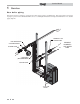
Service Manual 2 Maintenance Inspect ignition and flame sense electrodes Figure 2-2 Burner Assembly - Model 400 1. Remove the ignition and flame sense electrodes from the boiler heat exchanger access cover. 2. Remove any deposits accumulated on the ignition/flame sense electrode using sandpaper. If the electrodes cannot be cleaned satisfactorily, replace with new ones. AIR / GAS ARM 3. Replace ignition/flame sense electrode, making sure gasket is in good condition and correctly positioned.
Service Manual 2 Maintenance (continued) Check flame signal 1. At high fire the flame signal shown on the display should be at least 10 microamps. 2. A lower flame signal may indicate a fouled or damaged flame sense electrode. If cleaning the flame sense electrode does not improve, ground wiring is in good condition, and ground continuity is satisfactory, replace the flame sense electrode. 3. See Section 3 - Troubleshooting in this manual for other procedures to deal with low flame signal.
Service Manual 2 Maintenance Test low water flow conditions NOTICE This test is to be carried out once the Knight XL boiler is completely piped in with adequate gas and water flow. Once the test is completed, ensure that the isolation valve is opened up to allow full water flow. Test procedure 1. Set the [SH1 SETPOINT:] set point to the max user set point (reference Section 10 of the Knight XL Installation and Operation Manual).
Service Manual 3 Troubleshooting WARNING Label all wires prior to disconnection when servicing controls. Wiring errors can cause improper and dangerous operation. Always disconnect power to the boiler before servicing. Failure to comply could result in severe personal injury, death, or substantial property damage. Never jumper (bypass) any device WARNING except for momentary testing as outlined in the Troubleshooting chart. Severe personal injury, death, or substantial property damage can result.
Service Manual 3 Troubleshooting Table 3-1 Troubleshooting Chart - No Display FAULT CAUSE CORRECTIVE ACTION • Check external line switch, fuse, or breaker. - No 120 vac supplied to unit. • Check position of ON/OFF switch. Turn switch to the ON position. • Check 120 vac through the ON/OFF switch. • Check wiring harness connection between display board and main control board. Connect harness at both points. No Display - No voltage through the switch. • Replace switch. - Bad display board.
Service Manual 3 Troubleshooting (continued) Checking temperature sensors The boiler temperature sensors (inlet water, outlet water, system water, flue, and outdoor air) are all resistance type devices. The following tables show the correct values for the sensors at various temperatures. Use an ohmmeter to read the resistance of the sensor at a known temperature.
Service Manual 3 Troubleshooting Table 3-3 Troubleshooting Chart - Noisy System FAULT CAUSE - Noisy Operation CORRECTIVE ACTION Supply gas problem. Natural gas • Refer to Section 7 - Gas Connections of the Knight pressures should be between 4 inches XL Installation and Operation Manual for detailed w.c. and 14 inches w.c. LP gas pressures information concerning the gas supply. should be between 8 inches w.c. and 14 inches w.c. - Gas/air mixture problem.
Service Manual 3 Troubleshooting (continued) Table 3-4 Troubleshooting Chart - Fault Messages Displayed on Boiler Interface FAULT DESCRIPTION CORRECTIVE ACTION • Reset the pressure switches. Gas Pressure SW (will require a manual reset once the condition has been corrected. Press the RESET button on the SMART SYSTEM display to reset.) - Either the optional manual reset low gas pressure switch or the optional manual reset high gas pressure switch tripped.
Service Manual 3 Troubleshooting Table 3-4 (continued from previous page) Troubleshooting Chart - Fault Messages Displayed on Boiler Interface FAULT DESCRIPTION CORRECTIVE ACTION APS: • Check the wiring connections to switch. Wires should be connected to the common and normally closed terminals. • Air intake lengths exceed the maximum allowed lengths. Refer to Section 3 - General Venting of the Knight XL Installation and Operation Manual for proper lengths.
Service Manual 3 Troubleshooting (continued) Table 3-4 (continued from previous page) Troubleshooting Chart - Fault Messages Displayed on Boiler Interface FAULT DESCRIPTION CORRECTIVE ACTION The unit has failed to prove main burner ignition after four (4) attempts. • Verify that the plastic hose from the gas valve to the air inlet is connected and is not damaged. • Verify that the vent/air intake pipes are correctly installed and that there are no obstructions.
Service Manual 3 Troubleshooting Table 3-4 (continued from previous page) Troubleshooting Chart - Fault Messages Displayed on Boiler Interface FAULT DESCRIPTION CORRECTIVE ACTION • Adjust the set point of the auto reset limit to a higher setting up to a maximum of 200°F. Reference the Knight XL Installation and Operation Manual for adjusting procedures. • Verify that the system is full of water and that all air has been properly purged from the system.
Service Manual 3 Troubleshooting (continued) Table 3-4 (continued from previous page) Troubleshooting Chart - Fault Messages Displayed on Boiler Interface FAULT DESCRIPTION CORRECTIVE ACTION • Replace the main control board if necessary. • If 120 vac is present on a call for heat and the boiler pump is not operating, replace the pump. Outlet MRHL (cont’d) • If the system pump is a variable speed pump, ensure that the system flow is not less than the boiler flow.
Service Manual 3 Troubleshooting Table 3-4 (continued from previous page) Troubleshooting Chart - Fault Messages Displayed on Boiler Interface FAULT DESCRIPTION Sensor Shorted (will require a manual reset once the condition has been Either the inlet water or outlet water corrected. Press the RESET temperature sensor has been shorted. button on the SMART SYSTEM display to reset.) CORRECTIVE ACTION • Check the sensors and their associated wiring. Repair or replace the sensor or wiring if damaged.
Service Manual 3 Troubleshooting (continued) Table 3-4 (continued from previous page) Troubleshooting Chart - Fault Messages Displayed on Boiler Interface FAULT DESCRIPTION Flue Sensor Fault (will require a manual reset once the condition has been The control reads the flue sensor as open corrected. Press the RESET or shorted. button on the SMART SYSTEM display to reset.) CORRECTIVE ACTION • Check wiring to sensor. Make sure wiring is connected and not damaged.
Service Manual 3 Troubleshooting Table 3-4 (continued from previous page) Troubleshooting Chart - Fault Messages Displayed on Boiler Interface FAULT DESCRIPTION CORRECTIVE ACTION • Inspect the heat exchanger. Reference page 32 of this manual for the procedure on how to clean the flue side of the heat exchanger. Flue Temp High • Inspect the flue sensor and associated wiring.
Service Manual 3 Troubleshooting (continued) Table 3-4 (continued from previous page) Troubleshooting Chart - Fault Messages Displayed on Boiler Interface FAULT DESCRIPTION CORRECTIVE ACTION • Check set point of the external control. Rem Ctrl Flt External control is cycling too often. • Check the wiring between the external control and the unit. • Replace the control.
Service Manual 3 Troubleshooting Combustion Analysis Procedure Table 3-5 Flue Products 1. Turn the main power off to the boiler by placing the “On/ Off” switch in the OFF position. Natural Gas 2. Remove the flue temperature sensor from the flue pipe connection. Note: Combustion measurements will be made at this point. 3. Turn the main power on to the boiler by placing the “On/Off” switch in the ON position. CO2 O2 CO2 O2 8.0% - 10% 3.0% - 6.5% 9.0% - 11% 4.1% - 6.9% 8.
Service Manual 3 Troubleshooting (continued) Gas valve adjustment procedure Figure 3-3 Gas Valve Adjustment: Model 501 If adjustment of the gas valve is deemed necessary, use the following procedures: (Note: The procedures below are model specific.) CAUTION Under normal operating conditions this valve should not need adjusting. Model 400 Locate the throttle adjustment screw on the top of the gas valve, see FIG. 3-2.
Revision Notes: Revision A (ECO #C05747) initial release. Reflects the new model numbers for the Knight XL upgrade. Revision B (ECO #C06234) reflects changes made to the Service Notification parameter. Revision C (ECO #C07981) reflects changes made to the parameter table, parameter descriptions, updates to the troubleshooting chart, and the addition of the O-temp HEX switch. Revision D (ECO #C09197) reflects updates made to the SMART SYSTEM control (ECR #R04523).