FB-SER Rev B Service Manual Models: 1.5 - 2.0 - 2.5 - 3.0 - 3.5 WARNING This manual must only be used by a qualified heating installer / service technician. Read all instructions, including this manual and the Crest Installation and Operation Manual, before installing. Perform steps in the order given. Failure to comply could result in severe personal injury, death, or substantial property damage. Save this manual for future reference.
Contents CONTENTS........................................................................ 2 Hazard Definitions .............................................................. 2 PLEASE READ BEFORE PROCEEDING ........................ 3 Handling Ceramic Fiber Materials ...................................... 3 When servicing boiler ................................................... 4 Boiler operation............................................................ 4 Boiler water .....................................
Service Manual Please read before proceeding WARNING Installer – Read all instructions, including this manual and the Crest Installation and Operation Manual, before installing. Perform steps in the order given. NOTICE User – This manual is for use only by a qualified heating installer/service technician. Refer to the Crest User’s Information Manual for your reference. Have this boiler serviced/inspected by a qualified service technician at least annually.
Service Manual Please read before proceeding When servicing boiler – • To avoid electric shock, disconnect electrical supply before performing maintenance. • To avoid severe burns, allow boiler to cool before performing maintenance. Boiler operation – • Do not block flow of combustion or ventilation air to the boiler. • Should overheating occur or gas supply fail to shut off, do not turn off or disconnect electrical supply to circulator.
Service Manual What is in this manual? Service Maintenance Near boiler piping • Accessing programming mode and locating menus (See separate guide covering the PC interface.
Service Manual 1 Service Boiler piping This piping reference is included to specify the Boiler Piping specific to the Crest boiler. This piping scheme is important for proper operation of the SMART TOUCH control. See the Crest Installation and Operation Manual for more detailed piping diagrams.
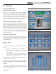
Service Manual 1 Service (continued) The Home Screen displays status, modulation rate, outlet water temperature, inlet water temperature, flue temperature, system supply temperature, system return temperature, outdoor air temperature, and domestic hot water tank temperature. The boiler can be started and stopped by pressing the ON/OFF button. The Boiler Status Screen and Main Menu Screen can be accessed by pressing the appropriate button.
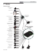
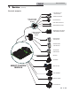
Service Manual 1 Service Control inputs HWG THERMOSTAT / SENSOR ENABLING DEVICE CASCADE LOW VOLTAGE CONNECTION BOARD LOUVER PROVING SWITCH SYSTEM SENSOR SUPPLY SYSTEM SENSOR RETURN OUTDOOR SENSOR MODBUS BOARD SEQUENCER / BUILDING MANAGMENT SYSTEM AUX SWITCH 1 & 2 SMART CONTROL MODULE 0-10 INPUT FROM SYSTEM PUMP INLET TEMPERATURE SENSOR OUTLET TEMPERATURE / HI-LIMIT SENSOR FLUE GAS SENSOR INLET AIR SENSORS AIR PRESSURE SWITCH MANUAL RESET HIGH LIMIT FLAME SENSOR 1 & 2 BLOCKED DRAIN SWITCH GAS PR
Service Manual 1 Service (continued) Control outputs 0-10V OUTPUT TO BOILER PUMP ALARM CONTACTS LOW VOLTAGE CONNECTION BOARD LOUVER RELAY RUN TIME CONTACTS BOILER RATE OUTPUT N L 120V SUPPLY LINE VOLTAGE TERMINAL STRIP SEQUENCER / BUILDING MANAGMENT SYSTEM BOILER PUMP DHW PUMP MAX. 1.
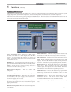
Service Manual 1 Service General Operation Figure 1-1 Home Screen How the boiler operates The Crest uses an advanced stainless steel heat exchanger and electronic control module that allows fully condensing operation. The blowers pull in air and push flue products out of the boiler through the heat exchanger and flue piping. The control module regulates blower speeds to control the boiler firing rate.
Service Manual 1 Service (continued) Figure 1-4 Setup Screen Saving parameters (reference the Parameter Table Table 1B on pages 13 - 17 of this manual) To adjust and save parameters (reference FIG. 1-5): To change a parameter, use the arrows next to the parameter list on the Menu Screen to highlight the desired parameter, then press SELECT. A short description of the parameter and its current setting are then displayed on the bottom half of the screen.
Service Manual 1 Service Table 1A Sequence of Operation Sequence of operation Note: This unit is equipped with two (2) gas train systems. Gas Train 1 will fire first. If the demand cannot be met by the first gas train, the second gas train (Gas Train 2) will fire. 1. Upon a call for heat, the control turns on the appropriate pumps (system and boiler pumps for a space heating call, HW pump for a domestic hot water call). 2.
Service Manual 1 Service (continued) Parameter table Table 1B This table lists SMART TOUCH control module parameters and where to access them OUTDOOR RESET SETPOINTS INITIAL SETUP Menu A B C Sub Item Parameter Name (as shown on the LCD screen) Max Default User See Min Page Value Value Value Access Installer Access 1 Clock 18 N/A N/A N/A Yes Yes 2 Date 18 N/A N/A N/A Yes Yes 3 SH Setpoint 18 32 185 120 Yes Yes 4 HWG Tank Setpoint 18 32 185 120 Yes Yes 5 MRHL
Service Manual 1 Service Parameter table Table 1B (continued from previous page) This table lists SMART TOUCH control module parameters and where to access them BMS RAMP DELAY OUTDOOR RESET Menu C D E 14 Sub Item Parameter Name (as shown on the LCD screen) See Min Page Value Max Default User Installer Value Value Access Access 7 Boost Time 20 0 250 20 No Yes 8 Boost Temperature 20 0 25 0 No Yes 9 Shift OA Reset Curve 20 -27 27 0 No Yes 1 Ramp Delay Mode 20
Service Manual 1 Service (continued) Parameter table Table 1B (continued from previous page) This table lists SMART TOUCH control module parameters and where to access them SH NIGHT SETBACK ADVANCED SETUP Menu F G Sub Item Parameter Name (as shown on the LCD screen) See Min Page Value Max Default User Installer Value Value Access Access 1 Temperature Units 21 °F °C °F Yes Yes 2 LCD Backlight Time 21 0 255 240 Yes Yes 3 Freeze Protection; Pump On 21 -22 45 44.
Service Manual 1 Service Parameter table Table 1B (continued from previous page) This table lists SMART TOUCH control module parameters and where to access them HWG NIGHT SETBACK Menu CASCADE MOD BUS H I J 16 Sub Item Parameter Name (as shown on the LCD screen) See Min Page Value Max Default User Installer Value Value Access Access 1 HWG Night Setback Offset Temp 22 0 90 0 No Yes 2 HWG Night Setback Mon End 22 N/A N/A N/A No Yes 3 HWG Night Setback Mon Begin 22 N/A
Service Manual 1 Service (continued) Parameter table Table 1B (continued from previous page) This table lists SMART TOUCH control module parameters and where to access them SERVICE NOTIFICATION PUMPS Menu K L Sub Item Parameter Name (as shown on the LCD screen) See Min Page Value Max Default User Installer Value Value Access Access 1 Boiler Pump Delay 24 0.5 2400 30 No Yes 2 Boiler Pump Anti-Seize Time 24 0 40 0.
Service Manual 1 Service Viewable and changeable control parameters See Table 1B on pages 13 - 17 of this manual for parameter references listed in this section. The parameter references listed in this section will not appear on the LCD screen. NOTICE CAUTION Before changing parameters, note the settings so that the unit can be returned to its original operating parameters. A: Initial Setup Clock and Date The control uses an internal clock for the night setback feature and for logging of events.
Service Manual 1 Service (continued) HWG Minimum User Set Point C: Outdoor Reset This setting controls the minimum user set point for the tank temperature. The installer can adjust this by accessing parameter B10. SH Set Point at Low Outdoor Temperature HWG Maximum User Set Point This setting controls the maximum user set point for the tank temperature. The installer can adjust this by accessing parameter B11.
Service Manual 1 Service Outdoor Air Shutdown Differential Shift OA Reset Curve The outdoor air shutdown differential parameter is the number of degrees below parameter C5 the outdoor air temperature must go before the boiler will respond to a SH demand. This parameter can be changed by the installer by accessing parameter C6. The shift reset curve parameter shifts the actual set point above or below the calculated set point by the number of degrees in this parameter.
Service Manual 1 Service (continued) E: BMS BMS Set Point at Maximum Volts BMS (Active / Inactive) When programmed for BMS control through the 0 - 10V BMS input or through ModBus and the BMS Type is programmed as SETPOINT, the set point represented by the Volts at Maximum parameter (E8) is set by parameter E10. The set point or modulation of the boiler may be controlled through the 0 - 10V BMS input or through ModBus. When parameter E1 set to INACTIVE, the 0 - 10V input will be ignored.
Service Manual 1 Service Freeze Protection Burner On HWG Rate Liming (NOT AVAILABLE AT THIS TIME) If running the pumps does not prevent the inlet temperature from falling closer to freezing, the SMART TOUCH control will fire the burner at low fire if in the ON state. The installer can adjust the temperature at which the burner fires by adjusting parameter F4. This parameter determines the maximum rate to be used when heating a HWG tank.
Service Manual 1 Service (continued) I: ModBus Cascade Off-On Differential ModBus (Active / Inactive) This parameter determines how much the temperature must go below the turn off temperature (Set point + Offset) before the lead boiler turns on. This parameter can be adjusted by the installer by accessing parameter J4. When BMS is set to ACTIVE (see BMS Active / Inactive) and the boiler is being controlled through ModBus, set parameter I1 to ACTIVE. Otherwise, set the ModBus parameter to INACTIVE.
Service Manual 1 Service Minimum Next On Time System Pump Mode In order to reduce the risk of temperature overshoot with a Cascade, this parameter defines the minimum time delay from starting one unit until the next unit may be started. The installer can adjust this time delay by accessing parameter J8. The SMART TOUCH control is able to control the system pump in 5 different ways.
Service Manual 1 Service (continued) L: Service Notification Service Notification in Months When the boiler control determines that a scheduled service is due based on the months of installation, the boiler display will turn yellow and a new status screen will appear informing the installer that maintenance is required. This parameter is adjustable by the installer by accessing parameter L1.
Service Manual 1 Service Cascade Screen Figure 1-8 Cascade Screen The Cascade Screen provides the status of the Cascade System. This screen is only accessible when the boiler is the Leader of an active Cascade. There are many items displayed on the Cascade Screen. Among them is the Boiler Power Level Indicators. For each boiler present in the Cascade a power level indicator will be present above its corresponding Cascade address.
Service Manual 1 Service (continued) Graph Screen The Graph Screen consists of two (2) different screens. The First screen is the Parameter Selection Screen. By pressing the up and down arrow keys the desired parameter can be selected. When the SELECT button is pressed the parameter will appear in the bottom half of the first screen. If a parameter is selected by mistake, it can be de-selected by highlighting the parameter and pressing the SELECT button.
Service Manual 1 Service History Screen The History Screen shows the status of various counters and faults. Within the History Screen there are three separate screens. These screens are the “Lockout Faults”, “Blocking Faults” and “Runtime History”. The default screen is the “Lockout Faults” screen. This screen allows you to view the last ten (10) lockout faults. Preceded by each fault is the date and time of when the fault occurred. The lockout faults can be reset by pressing the RESET FAULTS button.
Service Manual 1 Service (continued) History Screen The third screen is the “Runtime History”. There are several pieces of information that are displayed on this screen. Items that can be viewed on this screen are as follows: • • • • • • • • Power hours – Shows the number of hours the control has been powered on since the last reset. Running hours – Shows the number of hours that the boiler has been firing since the last reset.
Service Manual 1 Service (continued) Service Screen The Service Screen allows the integrated control to override all other heat demands and operate Valve 1 and Valve 2 at high fire and low fire conditions. To place the boiler into Service Mode, press the START button. As specified above the integrated control will override all other heat demands, however, all safeties will be active.
Service Manual 2 Maintenance Maintenance and annual startup Table 2A Service and Maintenance Schedules Service technician (see the following pages for instructions) Owner maintenance (see the Crest User’s Information Manual for instructions) General: • Address reported problems, if any • Inspect interior; clean and vacuum if necessary; • Check boiler area Daily • Check pressure/temperature gauge • Clean condensate trap and fill with fresh water • Check for leaks (water, gas, flue, condensate) • V
Service Manual 2 Maintenance WARNING Follow the service and maintenance procedures given throughout this manual and in component literature shipped with the boiler. Failure to perform the service and maintenance could result in damage to the boiler or system. Failure to follow the directions in this manual and component literature could result in severe personal injury, death, or substantial property damage. WARNING The boiler should be inspected annually only by a qualified service technician.
Service Manual 2 Maintenance (continued) Flue vent system and air piping 1. Visually inspect the entire flue gas venting system and air piping for blockage, deterioration or leakage. Repair any joints that show signs of leakage. Verify that air inlet pipe is connected and properly sealed. 2. Verify that boiler vent discharge and air intake are clean and free of obstructions.
Service Manual 2 Maintenance Inspect ignition sense electrodes and flame 1. Remove the ignition and both flame sense electrodes from the burner plate. 2. Remove any deposits accumulated on the ignition/ flame sense electrodes using sandpaper. If the electrodes cannot be cleaned satisfactorily, replace with new ones. 3. Replace ignition/flame sense electrodes, making sure the gaskets are in good condition and correctly positioned. Check ignition ground wiring 1.
Service Manual 2 Maintenance Review with owner (continued) 1. Review the Crest User’s Information Manual with the owner. 2. Emphasize the need to perform the maintenance schedule specified in the Crest User’s Information Manual (and in this manual as well). 3. Remind the owner of the need to call a licensed contractor should the boiler or system exhibit any unusual behavior. 4.
Service Manual 3 Troubleshooting WARNING WARNING Label all wires prior to disconnection when servicing controls. Wiring errors can cause improper and dangerous operation. Always disconnect power to the boiler before servicing. Failure to comply could result in severe personal injury, death, or substantial property damage. Never jumper (bypass) any device except for momentary testing as outlined in the Troubleshooting chart. Severe personal injury, death, or substantial property damage can result.
Service Manual 3 Troubleshooting (continued) Table 3A Troubleshooting Chart - No Display FAULT CAUSE - No 120 vac supplied to unit. CORRECTIVE ACTION • Check external line switch, fuse, or breaker. • Check position of ON/OFF switch. Turn switch to the ON position. • Check 120 vac through the ON/OFF switch. • Check wiring harness connection between display board and main control board. Connect harness at both points. No Display - No voltage through the switch. • Replace switch. - Bad display board.
Service Manual 3 Troubleshooting Checking temperature sensors The boiler temperature sensors (inlet water, outlet water, system water, flue, and outdoor air) are all resistance type devices. The following tables show the correct values for the sensors at various temperatures. Use an ohmmeter to read the resistance of the sensor at a known temperature.
Service Manual 3 Troubleshooting (continued) Table 3F Troubleshooting Chart - Noisy System FAULT CAUSE CORRECTIVE ACTION - Supply gas problem. Natural and LP gas • Refer to Section 6 - Gas Connections of the Crest pressures should be between 4 inches w.c. Installation and Operation Manual for detailed (1.0 kPa) and 14 inches w.c. (3.5 kPa). information concerning the gas supply. - Gas/air mixture problem.
Service Manual 3 Troubleshooting Table 3G Troubleshooting Chart - Fault Messages Displayed on Boiler Interface FAULT DESCRIPTION Gas Pressure SW Open (will require a manual reset once the condition Either the low gas pressure switch or one of has been corrected. Press the high gas pressure switches tripped. the RESET button on the SMART TOUCH display to reset.) Low Water Cutoff Open (will require a manual reset once condition has been corrected.
Service Manual 3 Troubleshooting (continued) Table 3G (continued from previous page) Troubleshooting Chart - Fault Messages Displayed on Boiler Interface FAULT Anti-cycling DESCRIPTION CORRECTIVE ACTION The main control board has received a call for heat too quickly after the previous call for heat has ended. • The control board will release the call for heat after a set time period. The unit has failed to prove main burner ignition. It will require a manual reset before attempting to fire again.
Service Manual 3 Troubleshooting Table 3G (continued from previous page) Troubleshooting Chart - Fault Messages Displayed on Boiler Interface FAULT DESCRIPTION CORRECTIVE ACTION Flame Out of Sequence 1 • Check supply voltage for proper polarity. (will require a manual The flame detector 1 circuit is seeing a flame reset once the condition • Check external wiring for voltage feedback. signal while no flame is present. has been corrected. • Check the internal wiring for bad connections.
Service Manual 3 Troubleshooting (continued) Table 3G (continued from previous page) Troubleshooting Chart - Fault Messages Displayed on Boiler Interface FAULT DESCRIPTION CORRECTIVE ACTION • Inspect flame rod 2 and associated wiring for damage and connection. Reference page 34 of this manual for removal and cleaning procedures. Replace if necessary. • Check for proper electrical grounding of unit. Flame Failure Running 2 • Check incoming supply gas pressure. Natural and L.P.
Service Manual 3 Troubleshooting Table 3G (continued from previous page) Troubleshooting Chart - Fault Messages Displayed on Boiler Interface FAULT DESCRIPTION CORRECTIVE ACTION • Verify that the system is full of water and that all air has been properly purged from the system. • Verify that the boiler is piped properly into the heating system. Refer to Section 5 - Hydronic Piping of the Crest Installation and Operation Manual for the proper piping methods for the Crest boiler.
Service Manual 3 Troubleshooting (continued) Table 3G (continued from previous page) Troubleshooting Chart - Fault Messages Displayed on Boiler Interface FAULT DESCRIPTION CORRECTIVE ACTION • Vent/air intake lengths exceed the maximum allowed lengths. Refer to Section 2 - General Venting of the Crest Installation and Operation Manual for proper lengths.
Service Manual 3 Troubleshooting Table 3G (continued from previous page) Troubleshooting Chart - Fault Messages Displayed on Boiler Interface FAULT DESCRIPTION Louver Proving Sw Open (will require a manual reset once the condition An optional remote proving switch is not has been corrected. Press making. the RESET button on the SMART TOUCH display to reset.) CORRECTIVE ACTION • Check function of remote devices. • Check for loose or misplaced jumper if proving switch is not installed.
Service Manual 3 Troubleshooting (continued) Table 3G (continued from previous page) Troubleshooting Chart - Fault Messages Displayed on Boiler Interface FAULT Outlet Temp High (continued) DESCRIPTION Outlet water temperature has exceeded the maximum outlet water temperature. CORRECTIVE ACTION • Verify that the boiler pump is set to the proper speed or that the boiler pump is the proper size.
Service Manual 3 Troubleshooting Table 3G (continued from previous page) Troubleshooting Chart - Fault Messages Displayed on Boiler Interface FAULT DESCRIPTION CORRECTIVE ACTION • Check the sensors and their associated wiring. Repair or replace the sensor or wiring if damaged. (will require a manual reset once the condition Either the inlet water or outlet water • Measure the resistance of the sensors and compare has been corrected. Press temperature sensor has been disconnected.
Service Manual 3 Troubleshooting (continued) Table 3G (continued from previous page) Troubleshooting Chart - Fault Messages Displayed on Boiler Interface FAULT DESCRIPTION CORRECTIVE ACTION • Check the wiring connections to switch. Wires should be connected to the common and normally open terminals. • Remove switch and check for blockage in the orifice. • Vent/air intake lengths exceed the maximum allowed lengths.
Service Manual 3 Troubleshooting Table 3G (continued from previous page) Troubleshooting Chart - Fault Messages Displayed on Boiler Interface FAULT DESCRIPTION CORRECTIVE ACTION • Wait 15 minutes and try again. Too Many Too many manual resets have occurred • Turn power off to unit, wait 30 seconds and then turn Resets - Try Later during a 15 minute period. power back on. Internal Fault The main control board has detected an • Replace the main control board. internal fault.
Service Manual 3 Troubleshooting (continued) Table 3G (continued from previous page) Troubleshooting Chart - Fault Messages Displayed on Boiler Interface FAULT DESCRIPTION CORRECTIVE ACTION • Verify that the system is full of water and that all air has been properly purged from the system. Outlet Temp Shutdown • Verify that the boiler is piped properly into the heating system.
Service Manual 3 Troubleshooting Combustion Analysis Procedure 1. Turn the main power off to the boiler by placing the “On/Off” switch in the OFF position. 2. Remove the flue temperature sensor from the flue collector. Note: Combustion measurements will be made at this point. 3. Turn the main power on to the boiler by placing the “On/Off” switch in the ON position. 4. Navigate to the Service Screen from the Home Screen by pressing the MAIN MENU button and then the SERVICE button. 5.
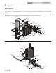
Service Manual 3 Troubleshooting (continued) Gas valve adjustment procedure CAUTION Figure 3-3 Gas Valve Adjustment: Model 2.5 Under normal operating conditions this valve should not need adjusting. Locate the throttle adjustment screw on the gas valve. For Models 1.5 and 2.0 see FIG. 3-2, for Model 2.5 see FIG. 3-3 and for Models 3.0 and 3.5 see FIG. 3-4. Using a screwdriver, turn the screw a 1/4 turn counterclockwise to increase CO2 levels or a 1/4 turn clockwise to decrease CO2 levels.
3 54 Troubleshooting NOTES
NOTES 55
Revision Notes: Revision A (ECO #C08179) initial release. Revision B (ECO C08436) reflects changes made to the parameter table, notice added to the parameter descriptions, changed out the screens on FIG.’s 1-8 and 1-14.