Installation & Operation Manual Models: ER152, ER202, ER252, ER302, and ER402 WARNING: This manual supplies information for the installation, operation, and servicing of the appliance. It is strongly recommended that this manual and the EnergyRite Service Manual be reviewed completely before proceeding with an installation. Perform steps in the order given. Failure to comply could result in severe personal injury, death, or substantial property damage. Save this manual for future reference.
Installation & Operation Manual Contents Hazard definitions . . . . . . . . . . . . . . . . . . . . . . . . . . . . . . . . . . . . . . . . . . . . . . . . . 2 Please read before proceeding . . . . . . . . . . . . . . . . . . . . . . . . . . . . . . . . . . . . . . . 3 Ratings . . . . . . . . . . . . . . . . . . . . . . . . . . . . . . . . . . . . . . . . . . . . . . . . . . . . . . . . . . 5 The EnergyRite -- How it works . . . . . . . . . . . . . . . . . . . . . . . . . . . . . . . . . . . . . . . 6 1.
Installation & Operation Manual Please read before proceeding NOTICE This is a gas appliance and should be installed by a licensed electrician and/or certified gas supplier. Service must be performed by a qualified service installer, service agency or the gas supplier. WARNING If the information in these instructions is not followed exactly, a fire or explosion may result causing property damage, personal injury, or death.
Installation & Operation Manual Please read before proceeding Spa and hot tub safety – Codes – The following safety rules must be observed while operating spa or hot tub. This pool heater has been designed and certified under the latest edition of Z21.56/CSA 4.7 Gas Fired Pool Heater Standard, including applicable addenda. 1. Spa or hot tub water temperatures should never exceed 104°F (40°C). A temperature of 100°F (38°C) is considered safe for a healthy adult.
Installation & Operation Manual Ratings Model Number Note: Change “N” to “L” for Propane gas models. Input Btu/hr Gas Pool Heater Water Content Connections Gallons Vent/Air Size Maximum Working Pressure (PSI) (Note 3) Add suffix “-A” for ASME models. ASME NON-ASME (NPT) Conventional DirectAire (Note 2) E-Rite (Note 2) ASME NON-ASME ERN152 150,000 0.58 0.83 3/4" 5" 4" 4" 125 50 ERN202 199,999 0.58 0.84 3/4" 5" 4" 4" 125 50 ERN252 250,000 0.59 0.
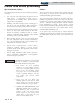
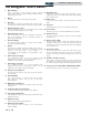
Installation & Operation Manual The EnergyRite - How it works... 1. Heat exchanger Allows pool water to flow through specially designed tubes for maximum heat transfer, while providing protection against flue gas corrosion. 2. Blower The blower provides air to mix with gas in the burners. 3. Gas valve The gas valve is a single stage referencing valve. The valve senses the chamber pressure and regulates gas flow based on that signal. 4. 5. Outlet temperature sensor 19.
Installation & Operation Manual The EnergyRite - How it works...
Installation & Operation Manual 1 Determine pool heater location Location of pool heater 1. Locate the pool heater so that if water connections should leak, it will not result in damage to the area adjacent to the pool heater or to the structure. When such locations cannot be avoided, it is recommended that a suitable drain pan, adequately drained, be installed under the pool heater. The pan must not restrict combustion air flow.
Installation & Operation Manual 1 Determine pool heater location Combustion and ventilation air requirements for conventionally vented appliances and sidewall vented appliances TABLE - 1A CLEARANCES FROM COMBUSTIBLE CONSTRUCTION Location Clearances Right Side 3" (24" suggested for service) Provisions for combustion and ventilation air must be in accordance with the Air for Combustion and Ventilation Section of the latest edition of the National Fuel Gas Code, ANSI Z223.
Installation & Operation Manual 1 Determine pool heater location Figure 1-3_Combustion Air Through Ducts Figure 1-5_Combustion Air from Outside - Single Opening 2. 4. If combustion and ventilation air is taken from the outdoors using a duct to deliver the air to the equipment room, each of the two openings should be sized based on a minimum free area of one square inch per 2000 Btu/hr. Figure 1-4_Combustion Air from Interior Space 3.
Installation & Operation Manual 1 Determine pool heater location (continued) TABLE - 1B MINIMUM RECOMMENDED COMBUSTION AIR SUPPLY TO EQUIPMENT ROOM Model Number Outside Air from 2 Openings Directly from Outdoors Top Bottom Opening, in2 Opening, in2 Outside Air from 1 Opening Directly from Outdoors, in2 Inside Air from 2 Ducts Delivered from Outdoors Inside Air from 2 Ducts Delivered from Interior Space Top Opening, in2 Bottom Opening, in2 Top Opening, in2 Bottom Opening, in2 ER152 38 38 50
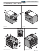
Installation & Operation Manual 2 General venting Vent system options Figure 2-1_Conventional Negative Draft Venting See page 17 for more details Figure 2-3_DirectAire Vertical Venting w/Vertical Air Inlet - See page 20 for more details 12 Figure 2-2_DirectAire Vertical w/Sidewall Air Inlet See page 21 for more details Figure 2-4_Power Sidewall Venting - See page 24 for more details
Installation & Operation Manual 2 General venting (continued) Figure 2-5_Power DirectAire Horizontal Venting - See page 25 for more details Figure 2-7_Outdoor Venting - See page 14 for more details Figure 2-6_E-Rite Sidewall Venting - See page 27 for more details This pool heater has six (6) venting options.
Installation & Operation Manual 2 General venting General Outdoor installation Vent installations for connection to gas vents or chimneys must be in accordance with “Venting of Equipment”, of the latest edition of the National Fuel Gas Code, ANSI Z223.1, in Canada, the latest edition of CAN/CGA - B149 Installation Codes for Gas Burning Appliances and Equipment or applicable provisions of the local building codes.
Installation & Operation Manual 2 General venting (continued) The outdoor pool heater must not be installed in an area that is enclosed by walls or a fence that will block free wind movement around the pool heater. Free movement of wind around the outdoor unit is required to carry away the flue products and provide combustion air. The flue outlet/combustion air inlet cap of an outdoor pool heater must not be installed closer than 10 feet from an inside corner of an L-shaped structure.
Installation & Operation Manual 2 General venting WARNING An Outdoor Installation, DirectAire Vent or an E-Rite Vent into dead air spaces such as alleys, atriums, and inside corners can cause recirculation of flue gases. Recirculation of flue gases will cause incomplete combustion, sooting, premature failure of the jacket, vent and heat exchanger as well as icing of the combustion air intake during operation in severe cold weather.
Installation & Operation Manual 3 Conventional venting A conventional negative draft venting system The negative draft in a conventional vent installation must be within the range of a negative 0.02 to 0.08 inches water to ensure proper operation. All draft readings are made while the unit is in stable operation (approximately 2 to 5 minutes). Remember that the draft in a conventional negative draft vent may vary seasonally.
Installation & Operation Manual 3 Conventional venting Common venting systems may be too large when an existing unit is removed. At the time of removal of an existing appliance, the steps below shall be followed with each appliance remaining connected to the common venting system placed in operation, while other appliances remaining connected to the common venting system are not in operation. a. Seal any unused opening in the common venting system. b.
Installation & Operation Manual 4 Vertical venting Vertical venting termination Figure 4-1_Vent Termination from Peaked Roof 10 Feet or Less From Ridge Figure 4-2_Vent Termination from Flat Roof 10 Feet or Less from Parapet Wall Figure 4-3_Vent Termination from Peaked Roof More Than 10 Feet From Ridge Figure 4-4_Vent Termination from Flat Roof More Than 10 Feet from Parapet Wall The vent terminal should be vertical and exhaust outside the building at least 2 feet above the highest point of the roof
Installation & Operation Manual 4 Vertical venting The venting system shall terminate at least 4 feet below, 4 feet horizontally from, or 1 foot above any door, window, or gravity air inlet into any building. Do not terminate the vent in a window well, stairwell, alcove, courtyard, or other recessed area. The vent cannot terminate below grade. The bottom of the vent terminal shall be located at least 12 inches above grade.
Installation & Operation Manual 4 Vertical venting (continued) Figure 4-5_DirectAire Vertical with Sidewall Venting Sidewall air inlet The sidewall air inlet cap kit is supplied as one of the DirectAire Vent kits which must be ordered from the manufacturer. This sidewall cap will supply combustion air for a single pool heater only. Figure 4-7_DirectAire Vertical Installation with Rooftop Combustion Air Vertical rooftop air inlet The air inlet arrangement as shown in FIG.
Installation & Operation Manual 4 Vertical venting Incorrect installation and/or location of the air inlet opening can allow the discharge of flue products to be drawn into the combustion process on the pool heater. This can result in incomplete combustion and potentially hazardous levels of carbon monoxide in the flue products. This will cause operational problems with the pool heater and possible spillage of flue products which can cause personal injury, death, or property damage.
Installation & Operation Manual 4 Vertical venting (continued) TABLE - 4A DIRECTAIRE VENT KITS DirectAire Model Conventional Air Inlet w/rooftop Number Vent Flue Size Pipe* air inlet CAUTION DirectAire w/sidewall vent cap ER152 5" 4" VDK3043 VDK3040 ER202 5" 4" VDK3043 VDK3040 ER252 6" 5" VDK3044 VDK3041 ER302 6" 5" VDK3045 VDK3042 ER402 6"** 5" VDK3045 VDK3042 *Minimum diameter, installer may increase diameter one pipe size for ease of installation if needed.
Installation & Operation Manual 5 Sidewall venting The power sidewall venting system Length of flue pipe Power sidewall venting with combustion air from the equipment room The maximum total equivalent length of flue pipe connected to the power sidewall cap cannot exceed 75 equivalent feet. Subtract 5 feet for each elbow in the vent. Do not exceed the limit for total equivalent vent pipe length.
Installation & Operation Manual 5 Sidewall venting (continued) Venting of flue products CAUTION The sidewall vent cap shall terminate at least 3 feet above any forced air inlet within 10 feet. The sidewall vent shall terminate at least 4 feet below, 4 feet horizontally from or 1 foot above any door, window, or gravity air inlet to the building. Do not terminate the sidewall vent in a window well, stairwell, alcove courtyard, or other recessed area. The sidewall vent can not terminate below grade.
Installation & Operation Manual 5 Sidewall venting The Power DirectAire Horizontal combustion air supply system has specific material and installation requirements. The air inlet pipe uses an adapter to supply combustion air and for connection directly to the pool heater. The combustion air inlet pipe will be a dedicated system with one air inlet pipe per pool heater. The air inlet pipe must be connected to a combustion air inlet cap as specified in this section.
Installation & Operation Manual 5 Sidewall venting (continued) TABLE - 5B POWER DIRECTAIRE HORIZONTAL VENT KITS Model Number Flue Size ER152 4" 4" SVK3064 ER202 4" 4" SVK3064 ER252 5" 5" SVK3065 ER302 5" 5" SVK3066 ER402 6" 5" SVK3067 E-Rite sidewall venting system DirectAire Power DirectAire Inlet Pipe* Horizontal Kit *Minimum diameter, installer may increase diameter one pipe size for ease of installation if needed.
Installation & Operation Manual 5 Sidewall venting TABLE - 5C AIR SHUTTER ADJUSTMENT OPENING FOR E-RITE VENT SYSTEMS Model Number “A” Dimension Opening Chamber Pressure ER152 1 1/4" 1.4" ER202 1 1/4" 1.4" ER252 1 3/8" 1.4" ER302 1 9/16" 1.4" ER402 1 3/4" 1.4" The E-Rite Sidewall Vent kit includes recommendations to purchase and install specific sidewall vent terminations from recommended AL29-4C vent system manufacturers.
Installation & Operation Manual 5 Sidewall venting (continued) Sealing of venting materials The AL29-4C vent materials must be installed and sealed per the vent manufacturer’s installation instructions. The E-Rite Sidewall Vent System requires installation of a separate pipe to supply combustion air from outdoors directly to the pool heater.
Installation & Operation Manual 5 Sidewall venting When an E-Rite Sidewall Vent System is disconnected for any reason, the flue must be reassembled and resealed according to the vent manufacturer’s instructions to ensure that flue products will not be discharged into the equipment room or other occupied spaces in the building. The air inlet pipe must also be resealed to ensure that combustion air will be free of contaminants and supplied in proper volume.
Installation & Operation Manual 5 Sidewall venting (continued) The combustion air inlet caps for multiple unit installations must maintain the minimum 3 foot radius clearance below or horizontally from the closest flue outlet. Multiple flue outlet caps may be installed side by side and multiple air inlet caps may be installed side by side but the 3 foot radius minimum clearance between air inlet and flue outlet must be maintained.
Installation & Operation Manual 6 Gas connections Gas supply Gas connection Verify unit is supplied with the type of gas specified on the rating plate. This unit is orificed for operation up to 4000 feet altitude. Consult factory for installations above 4000 feet elevation. Safe operation of the unit requires properly sized gas supply piping. See the following data: TABLE - 6A INLET GAS PRESSURE Measured at the inlet pressure tap located upstream of the combination gas valve.
Installation & Operation Manual 6 Gas connections (continued) LP gas installations WARNING LP (propane) gas is heavier than air and will remain at floor level if there is a leak. Basements, crawl spaces, alcoves, and areas below ground level will serve as pockets for accumulation of leaking gas. Before lighting, sniff at floor level. If you smell gas, follow instructions on page 3 of this manual. Shut off gas at LP tank outside of the building. DO NOT operate appliance until leakage is corrected.
Installation & Operation Manual 7 Water connections This pool heater is equipped with an automatic, built-in bypass located in the front header. This bypass is flow actuated to maintain proper flow through the pool heater at flow rates of less than 100 GPM. If the water flow rate to the pool heater exceeds 100 GPM, an auxiliary bypass must be installed in the piping to the pool heater. See the Auxiliary Bypass section for piping and adjustment.
Installation & Operation Manual 7 Water connections (continued) Automatic chlorinators and chemical feeders All chemicals must be diluted into the pool or spa water before they are circulated through the pool heater. Any concentration of chlorine in the pool heater can cause damage to the unit. Do not place chlorine tablets or bromine sticks in the skimmer. High chemical concentrations will result when the pump is not running.
Installation & Operation Manual 8 Electrical connections This appliance is wired for 240 VAC service. The pool heater can be converted to 120 VAC by moving the jumper connector from the connector labeled 240 VAC to the connector labeled 120 VAC as shown in FIG. 8-1. The jumper connector is located inside the appliance on the left-hand side.
Installation & Operation Manual 8 Electrical connections (continued) Integrated controller High water temperature limit controls The pool heater is equipped with a microprocessor based adjustable digital integrated controller to provide ON/OFF operation. Operation is based on temperature input from an immersion sensor. The immersion temperature sensor senses inlet water temperature to the pool heater and is located in the inlet side of the front header.
Installation & Operation Manual 9 Start-up 38
Installation & Operation Manual 9 Start-up (continued) Energy saving recommendations 1. Keep the pool/spa covered when not in use. This will cut heating cost, reduce water evaporation, conserve chemicals and reduce load on the filtering system. 2. Reduce pool thermostat to 78°F (25°C) or lower, reduce spa temperature to 100°F (38°C). 3. Use an accurate pool/spa thermometer to monitor water temperature. 4.
Installation & Operation Manual 9 Start-up 4. Turn on gas supply at the manual gas cock, turn on LP gas at tank if required. 5. Turn the power switch to the “ON” position. 6. Ensure that the “ON/OFF” knob or the valve is in the “ON” position. 7. Set the electronic temperature control to call for heat. 8. Observe the gas supply pressure as all burners are firing. Ensure that inlet pressure is within the specified range.
Installation & Operation Manual 10 Operating information General Protection features How the pool heater operates High limit The EnergyRite uses a copper finned tube heat exchanger and an electronic control module. The blower provides both primary and secondary air to the burners and forces the flue products out of the combustion chamber and into the vent system. The combination gas valve both regulates the manifold pressure and provides gas to the manifold, which then supplies the burners.
Installation & Operation Manual 10 Operating information Auxiliary safety 1 and 2 Two auxiliary safeties may be connected to the control module. The control module will not initiate or will terminate a call for heat if either safety is open. The control module will show AUXILIARY SAFETY 1 OPEN or AUXILIARY 2 OPEN in the display. The control module will not initiate a call for heat until this condition is corrected.
Installation & Operation Manual 10 Operating information (continued) Sequence of operation OPERATION 1. Upon a call for heat, the control module will look at the high limit, the water pressure switch, and the auxiliary safeties. If any of these devices are open, the control module will not initiate an ignition sequence. 2. The control will enter the Pre-Purge Mode. After five seconds it will begin to look for the air pressure switch to be closed.
Installation & Operation Manual 10 Operating information EnergyRite control module Use the control panel (FIG. 10-1) to set temperatures, operating conditions, and monitor unit operation.
Installation & Operation Manual 10 Operating information (continued) Access modes Modes of operation Setup menu There are three modes of operation: 1) Off, 2) Pool, and 3) Spa. The factory default mode is Off. Additional features can be accessed and adjusted through the Setup Menu. Please reference the EnergyRite Service Manual for a detailed description of the Setup Menu. Off mode Service menu When in Off Mode the control will display CONTROL OFF and does not monitor any of the inputs.
Installation & Operation Manual 10 Operating information LABEL 2306 REV B Figure 10-2_Wiring Diagram 46
Installation & Operation Manual 10 Operating information (continued) Figure 10-3_Ladder Diagram 47
Installation & Operation Manual 11 ASME addendum The EnergyRite - How it works... 1. Heat exchanger Allows pool water to flow through specially designed tubes for maximum heat transfer, while providing protection against flue gas corrosion. 2. Outlet temperature sensor This sensor monitors outlet water temperature and will shut down the unit if this temperature gets too high. 3.
Installation & Operation Manual 11 ASME addendum (continued) Water connections Inlet and outlet connections Connection to the pool heater can be made with either 2" threaded pipe or a slip connection with 1 1/2" or 2" pipe. Two inch threaded pipe may be directly screwed into the flanged header connections for both inlet and outlet piping. Each pool heater is supplied with two sets of gaskets to allow a flanged compression attachment of either 2" or 1 1/2" copper pipe directly to the front header.
Installation & Operation Manual 11 ASME addendum Adjustment of auxiliary bypass Relief valve 1. Backwash and clean pool filters. 2. Start with the bypass valve in the half open position. 3. Start the pool heater. 4. Check the temperature rise across the pool heater (reference the Menu Descriptions - Delta T section of the EnergyRite Service Manual). 5. If the temperature rise across the pool heater is more than 15°F, close the bypass valve to increase flow to the pool heater.
NOTES 51
Revision Notes: Rev. B (ERP-I&O-Rev. B) reflects changes made to font on Page 24 and to Figure 10-2. Revision C (ECO C02053) reflects edits made to the E-Rite Sidewall Venting Section on Page 27. ERP-I&O-Rev.