
2 Owner manual

Installation & Operation Manual
5 Sidewall venting (continued)
27
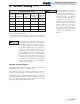
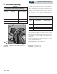
TABLE - 5B
POWER DIRECTAIRE HORIZONTAL
VENT KITS
Model
Number
Flue Size
DirectAire
Inlet Pipe*
Power DirectAire
Horizontal Kit
ER152 4" 4" SVK3064
ER202 4" 4" SVK3064
ER252 5" 5" SVK3065
ER302 5" 5" SVK3066
ER402 6" 5" SVK3067
*Minimum diameter, installer may increase diameter one
pipe size for ease of installation if needed.
The sidewall air inlet cap supplied in the Power DirectAire
Horizontal Vent kit is used to supply combustion air to a
single pool heater. Combustion air supply pipes from
multiple units can NOT be combined into a single air inlet
pipe and inlet point. The use of a sidewall air inlet cap other
than the manufacturer’s recommended cap may result in
operational problems with the unit or potentially hazardous
spillage of flue products which can cause personal injury,
death, or property damage.
For venting flue products horizontally to the outdoors,
follow all requirements in the installation instructions for
sidewall venting.
The termination point for the flue products must follow the
clearance requirements in the Sidewall Vent Termination -
Venting of Flue Products section.
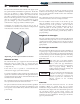
A barometric damper is required in the flue on Power
DirectAire Horizontal installations. The barometric
damper must be adjusted to maintain a negative draft
within the 0.02 to 0.08 inches water required for proper
operation. The barometric damper provides dilution air to
the vent system to prevent condensate formation.
CAUTION
Pool heaters which are shut down or will
not operate may experience freezing due
to convective air flow in the air inlet pipe
connected to the unit. If operated in
cold climates, continuous pump
operation is recommended to help
prevent freezing of pool water on
DirectAire systems. Proper freeze
protection must be provided. A pool
heater that is not in use in the winter
season must be properly drained and
winterized. See the Winterizing section
of the EnergyRite Service Manual.
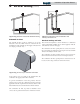
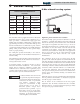
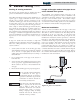
E-Rite sidewall venting system
Figure 5-5_E-Rite Sidewall Vent Installation
The E-Rite venting option provides an alternative to vent the
appliance to a sidewall under limited vent lengths without the
need for an external powered sidewall venter. The maximum
vent length of 20 equivalent feet allows for up to 15 feet of
horizontal vent length between a sidewall and the pool heater,
and includes one 90° elbow fitted at the flue and air inlet
connections on the cabinet. A listed AL29-4C stainless steel
sealed vent system suitable for venting direct vent applications
must be used. Refer to page 28 of this manual for specific
recommendations from listed AL29-4C vent system
manufacturers.
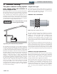
The combustion air fan of the pool heater forces the flue
products to the outside through the vent terminal while at the
same time drawing in combustion air from the outside through
the air inlet terminal. Both inlet and vent terminals must be
located in the same pressure zone, and a specific dimensional
relationship of intake to exhaust terminal orientation must also
be followed. This is sometimes referred to as a “balanced flue”
or “direct vent” application. Since both terminals are in the
same pressure zone, any pressure exerted on one terminal is also
exerted on the other terminal, canceling out identical wind
pressure effects.
When this option is used, an optional E-Rite Sidewall Vent kit
must be purchased and installed. See Installation of Optional
Vent Kits on page 16 of this manual.
The air shutter on the combustion air fan may require
adjustment after the E-Rite Sidewall Vent kit is installed.
Reference Table 5C - Air Shutter Adjustment Opening for E-Rite
Vent Systems on page 28 of this manual.