KBX-SER Rev E Service Manual Models: 399 - 800 WARNING This manual must only be used by a qualified heating installer / service technician. Read all instructions, including this manual and the Knight XL Installation and Operation Manual, before installing. Perform steps in the order given. Failure to comply could result in severe personal injury, death, or substantial property damage. Save this manual for future reference.
Contents CONTENTS . . . . . . . . . . . . . . . . . . . . . . . . . . . . . . . . . . . . 2 Hazard Definitions . . . . . . . . . . . . . . . . . . . . . . . . . . . . . . . 2 PLEASE READ BEFORE PROCEEDING . . . . . . . . . . . . 3 Handling Ceramic Fiber Materials . . . . . . . . . . . . . . . . . . . 3 When servicing boiler . . . . . . . . . . . . . . . . . . . . . . . . . . 4 Boiler operation . . . . . . . . . . . . . . . . . . . . . . . . . . . . . . 4 Boiler water . . . . . . . . . . . . . . . . . . . .
Service Manual Please read before proceeding WARNING Installer – Read all instructions, including this manual and the Knight XL Installation and Operation Manual, before installing. Perform steps in the order given. NOTICE User – This manual is for use only by a qualified heating installer/service technician. Refer to the Knight XL User’s Information Manual for your reference. Have this boiler serviced/inspected by a qualified service technician at least annually.
Service Manual Please read before proceeding When servicing boiler – • To avoid electric shock, disconnect electrical supply before performing maintenance. • To avoid severe burns, allow boiler to cool before performing maintenance. Boiler operation – • Do not block flow of combustion or ventilation air to the boiler. • Should overheating occur or gas supply fail to shut off, do not turn off or disconnect electrical supply to circulator.
Service Manual What is in this manual? Service Maintenance Near boiler piping • Service and maintenance schedules • Address reported problems • Inspect boiler area and boiler interior • Clean condensate trap • Check all piping for leaks • Check air openings • Flue vent system and air piping • Check water system • Check expansion tank • Check boiler relief valve • Inspect ignition electrode • Check ignition ground wiring • Check all boiler wiring • Check control settings • Perform start-up and checks • C
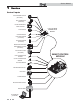
Service Manual 1 Service Near boiler piping This piping reference is included to specify the Near Boiler Piping specific to the Knight XL. This piping scheme is important for proper operation of the SMART SYSTEM control. See the Knight XL Installation and Operation Manual for more detailed piping diagrams.
Service Manual 1 Service (continued) The Knight XL display • Hold 5 seconds to enter code Input Mode (Menu Mode) • Press to move up one level in Menu Mode or to exit Menu Mode • Press to turn boiler off or back on SHUTDOWN • Press to select a menu item • Press after parameter programming to store parameter data • Press to exit Service Mode ENTER / RESET MENU / EXIT DISPLAY SCREEN SERVICE BUTTON PC CONNECTION PORT UP DOWN • Press to change boiler water temperature set point during normal operati
Service Manual 1 Service Control inputs GAS PRESSURE SWITCH (OPTIONAL) DHW THERMOSTAT (OPTIONAL) ROOM THERMOSTAT / ZONE CONTROL FLOW SWITCH LOW VOLTAGE CONNECTION BOARD SYSTEM SENSOR DHW TANK SENSOR (OPTIONAL) OUTDOOR SENSOR (OPTIONAL) SEQUENCER / BUILDING MANAGEMENT SYSTEM (OPTIONAL) LOW WATER CUTOFF (OPTIONAL) INLET TEMPERATURE SENSOR OUTLET TEMPERATURE SENSOR FLUE GAS SENSOR AIR PRESSURE SWITCH HIGH LIMIT FLAME SENSOR BLOCKED DRAIN SWITCH DISPLAY PANEL PC INTERFACE (OPTIONAL) 8 SMART CONTRO
Service Manual 1 Service (continued) Control outputs ALARM BELL LOW VOLTAGE CONNECTION BOARD AUX.
Service Manual 1 Service General Operation How the boiler operates Access modes The Knight XL uses an advanced stainless steel heat exchanger and an electronic control module that allows fully condensing operation. The blower pulls in gas and air and pushes flue products out of the boiler through the heat exchanger and flue piping. The control module regulates blower speed to control boiler firing rate.
Service Manual 1 Service (continued) Sequence of operation Table 1A Sequence of operation - space heating and DHW OPERATION DISPLAY 1. Upon a call for heat, the control turns on the appropriate pumps (system and boiler pumps for space heating call; DHW pump for DHW call). 2. The control connects 120 VAC to the blower. does not run at this time. BLR: Standby OUT: 123.8F(129) The blower • The manual reset high limit must be closed and reset.
Service Manual 1 Service Sequence of operation (continued) Table 1A (continued from previous page) Sequence of operation - space heating and DHW OPERATION DISPLAY 8. If the boiler is not part of a cascade, and the DHW call for heat remains active for more than 30 minutes, and the space heating call for heat is also active, then the control will turn on the boiler pump, turn off the DHW pump after 2 seconds, and resume modulating based on the space heating set point.
Service Manual 1 Service (continued) Display panel menu access Table 1B Use this procedure to access menus from the display panel BUTTON OPERATION DISPLAY COMMENTS ENTER/RES Press 1 time in normal operation BLR:OFF OUT:127.
Service Manual 1 Service Display panel parameter access Table 1C This is a typical example of accessing a parameter, shown for parameter I2, boiler pump delay BUTTON OPERATION DISPLAY COMMENTS This example shows how to access parameter I2, boiler pump delay. The first display shown is at the beginning of the menu listings, after entering the installer acess code.
Service Manual 1 Service (continued) Parameter table Table 1D This table lists SMART SYSTEM control module parameters and where to access them OUTDOOR AIR RESET DHW FUNCTIONS SETTINGS DATA LOGGING TEMPERATURE SETTING GENERAL MENU A B SUB ITEM DESCRIPTION USER ACCESS SEE PAGE DISPLAY MODIFY INSTALLER ACCESS DISPLAY MODIFY 1 Boiler Model 17 Yes No Yes No 2 User Code 17 Yes Yes Yes Yes 3 Date and Time 17 Yes Yes Yes Yes 4 Software Version 17 Yes No Yes No 5 Temper
Service Manual 1 Service Parameter table (continued) ANTI-CYCLING Table 1D (continued from previous page) This table lists SMART SYSTEM control module parameters and where to access them MENU G SUB ITEM CONTROL MODES CIRCULATION SERVICE PUMPS NOTIFICATION USER ACCESS INSTALLER ACCESS SEE PAGE DISPLAY MODIFY DISPLAY MODIFY 1 Anti-cycling Time 20 No No Yes Yes 2 Return Temperature Differential for Ending Anti-Cycling 20 No No Yes Yes 3 Ramp Delay On/Off 20 No No Yes Yes 21 N
Service Manual 1 Service Viewable and changeable control parameters CAUTION Before changing parameters, note the settings so that the unit can be returned to its original operating parameters. A: General Boiler model The control will display “Knight Boiler” as the model number because the same control is used on several models. This will be displayed when parameter A1 has been accessed. This parameter is not changeable.
Service Manual 1 Service SH Differential E: DHW settings The SH differential sets how many degrees below the turn off temperature the temperature has to go before the boiler will turn on. This parameter can only be changed by the installer by accessing parameter B5. The temperature range of this parameter is 0°F (0°C) to 54°F (30°C). The default value is 20°F (11°C).
Service Manual 1 Service (continued) Figure 1-1 Outdoor Air Reset Curve WATER TEMPERATURE SET POINT MAXIMUM RESET Default = 180°F USER SET POINT Default = 125°F MINIMUM RESET Default = 70°F Default = 25°F Default = 70°F OUTDOOR AIR AT MINIMUM RESET OUTDOOR TEMPERATURE OUTDOOR AIR AT MAXIMUM RESET Maximum air temperature Outdoor air shutdown When the outdoor air temperature rises to or above this point, the water temperature will be at its minimum setting (FIG. 1-1).
Service Manual 1 Service Boost temperature If a SH demand lasts longer than the programmed time delay setting (F9) and there have been no DHW demands, the control will increase the water temperature set point by the amount in this parameter. If the SH demand continues through another time period, the set point will be increased again. This will continue until either the SH demand ends, a maximum of 20 increases has occurred, or the maximum set point has been reached.
Service Manual 1 Service (continued) Figure 1-2 Ramp Delay Interval % RATE RAMP 6 RAMP 5 RAMP 4 RAMP 3 RAMP 2 RAMP 1 CALL FOR HEAT TIME 1 TIME 2 TIME 3 H: Control modes SH controlling sensor The SH controlling sensor parameter selects the sensor the control will use to regulate the boiler firing rate. This parameter is adjustable by the installer by accessing parameter H1.
Service Manual 1 Service Cascade offset Service notification running hours This parameter determines how much the temperature must go above set point before the lead boiler will turn off. This parameter can be adjusted by the installer by accessing parameter H5. The default value is 9.9°F (5°C).
Service Manual 2 Maintenance Maintenance and annual startup Table 2A Service and Maintenance Schedules Service technician (see the following pages for instructions) Owner maintenance (see the Knight XL User’s Information Manual for instructions) General: • Check boiler area • Address reported problems • Inspect interior; clean and vacuum if necessary; Daily • Clean condensate trap and fill with fresh water • Check pressure/temperature gauge • Check for leaks (water, gas, flue, condensate) ANNUAL
Service Manual 2 Maintenance WARNING Follow the Service and maintenance procedures given throughout this manual and in component literature shipped with the boiler. Failure to perform the service and maintenance could result in damage to the boiler or system. Failure to follow the directions in this manual and component literature could result in severe personal injury, death, or substantial property damage. WARNING The boiler should be inspected annually only by a qualified service technician.
Service Manual 2 Maintenance (continued) Flue vent system and air piping 1. Visually inspect the entire flue gas venting system and air piping for blockage, deterioration or leakage. Repair any joints that show signs of leakage. Verify that air inlet pipe is connected and properly sealed. 2. Verify that boiler vent discharge and air intake are clean and free of obstructions.
Service Manual 2 Maintenance Inspect ignition and flame sense electrodes Check burner flame 1. Remove the ignition and flame sense electrodes from the boiler heat exchanger access cover. 2. If the flame is unsatisfactory at either high fire or low fire, turn off boiler and allow boiler to cool down. Remove the burner and clean it thoroughly using a vacuum cleaner or compressed air. Do not use compressed air to clean burner if performed inside a building. 2.
Service Manual 2 Maintenance (continued) Figure 2-4 Burner Assembly - Models 600 - 800 AIR ARM Cleaning boiler heat exchanger 1. Shut down boiler: • Follow the “To Turn Off Gas to Appliance” instructions for the boiler in the Knight XL Installation and Operation Manual. • Do not drain the boiler unless it will be exposed to freezing temperatures. If using freeze prevention fluid in system, do not drain. 2. Allow time for the boiler to cool to room temperature if it has been firing. 3.
Service Manual 3 Troubleshooting WARNING Label all wires prior to disconnection when servicing controls. Wiring errors can cause improper and dangerous operation. Always disconnect power to the boiler before servicing. Failure to comply could result in severe personal injury, death, or substantial property damage. WARNING Never jumper (bypass) any device except for momentary testing as outlined in the Troubleshooting chart. Severe personal injury, death, or substantial property damage can result.
Service Manual 3 Troubleshooting (continued) Table 3A Troubleshooting Chart - No Display FAULT CAUSE - No 120 VAC supplied to unit. CORRECTIVE ACTION • Check external line switch, fuse, or breaker. • Check position of ON/OFF switch. Turn switch to the ON position. • Check 120 VAC through the ON/OFF switch. • Check wiring harness connection between display board and main control board. Connect harness at both points. No Display - No voltage through the switch. • Replace switch. - Bad display board.
Service Manual 3 Troubleshooting Checking temperature sensors The boiler temperature sensors (inlet water, outlet water, system water, flue, and outdoor air) are all resistance type devices. The following tables show the correct values for the sensors at various temperatures. Use an ohmmeter to read the resistance of the sensor at a known temperature. If the resistance of the sensor does not closely match its corresponding table, replace the sensor. Table 3B - Inlet/Outlet System Sensor Resistance vs.
Service Manual 3 Troubleshooting (continued) Table 3E Troubleshooting Chart - Noisy System FAULT CAUSE CORRECTIVE ACTION - Supply gas problem. Natural gas pressures • Refer to Section 7 - Gas Connections of the Knight should be between 4 inches w.c. (1.0 kPa) XL Installation and Operation Manual for detailed and 14 inches w.c. (3.5 kPa). LP gas information concerning the gas supply. pressures should be between 8 inches w.c. (2.0 kPa) and 14 inches w.c. (3.2 kPa).
Service Manual 3 Troubleshooting Table 3F Troubleshooting Chart - Fault Messages Displayed on Boiler Interface FAULT DESCRIPTION Either the optional manual reset low gas pressure switch or the optional manual reset high gas pressure switch tripped (not available on 399 models). Gas Pressure SW (will require a manual reset once the condition has been corrected. Press the RESET button on the SMART SYSTEM display to reset.) CORRECTIVE ACTION • Reset the pressure switches.
Service Manual 3 Troubleshooting (continued) Table 3F (continued from previous page) Troubleshooting Chart - Fault Messages Displayed on Boiler Interface FAULT Anti-cycling DESCRIPTION CORRECTIVE ACTION The main control board has received a call for heat too quickly after the previous call for heat has ended. • The control board will release the call for heat after a set time period.
Service Manual 3 Troubleshooting Table 3F (continued from previous page) Troubleshooting Chart - Fault Messages Displayed on Boiler Interface FAULT DESCRIPTION CORRECTIVE ACTION The unit was running and lost the flame signal. This condition occurred four (4) straight times on the 399 model or twice on the 500 - 800 models . • Inspect spark electrode and associated wiring for damage and connection. Reference page 26 of this manual for removal and cleaning procedures. Replace if necessary.
Service Manual 3 Troubleshooting (continued) Table 3F (continued from previous page) Troubleshooting Chart - Fault Messages Displayed on Boiler Interface FAULT DESCRIPTION CORRECTIVE ACTION The outlet water temperature has exceeded • Verify that the system is full of water and that all air the setting of the high limit. has been properly purged from the system. • Verify that the boiler is piped properly into the heating system.
Service Manual 3 Troubleshooting Table 3F (continued from previous page) Troubleshooting Chart - Fault Messages Displayed on Boiler Interface FAULT DESCRIPTION CORRECTIVE ACTION • Vent/air intake lengths exceed the maximum allowed lengths. Refer to Section 3 - General Venting of the Knight XL Installation and Operation Manual for proper lengths.
Service Manual 3 Troubleshooting (continued) Table 3F (continued from previous page) Troubleshooting Chart - Fault Messages Displayed on Boiler Interface FAULT DESCRIPTION CORRECTIVE ACTION The stack temperature has exceeded the set • Inspect the heat exchanger. Reference page 27 of parameters for the boiler. this manual for the procedure on how to clean the flue side of the heat exchanger. • Inspect the flue sensor and associated wiring.
Service Manual 3 Troubleshooting Table 3F (continued from previous page) Troubleshooting Chart - Fault Messages Displayed on Boiler Interface FAULT Temp O/Shoot (continued) DESCRIPTION CORRECTIVE ACTION Outlet water temperature has exceeded the maximum outlet water temperature. • Verify that the boiler pump is set to the proper speed or that the boiler pump is the proper size. Reference Section 6 - Hydronic Piping of the Knight XL Installation and Operation Manual for boiler pump specifications.
Service Manual 3 Troubleshooting (continued) Table 3F (continued from previous page) Troubleshooting Chart - Fault Messages Displayed on Boiler Interface FAULT DESCRIPTION CORRECTIVE ACTION While the unit is in Service Mode, the outlet • Establish a heating load to remove the heat from the temperature has exceeded 185°F. boiler loop. • Verify that the system is full of water and that all air has been properly purged from the system. • Verify that the boiler is piped properly into the heating system.
Service Manual 3 Troubleshooting Combustion Analysis Procedure Table 3H Flue Products 1. Turn the main power off to the boiler by placing the “On/Off ” switch in the OFF position. Natural Gas 2. Remove the flue temperature sensor from the flue pipe connection. Note: Combustion measurements will be made at this point. 3. Turn the main power on to the boiler by placing the “On/Off ” switch in the ON position. 4.
Service Manual 3 Troubleshooting (continued) Gas valve adjustment procedure Figure 3-3 Gas Valve Adjustment: Model 500 If adjustment of the gas valve is deemed necessary, use the following procedures: (Note: The procedures below are model specific.) CAUTION Under normal operating conditions this valve should not need adjusting. Model 399 Locate the throttle adjustment screw on the top of the gas valve, see FIG. 3-2.
Service Manual 4 Notes 42
Service Manual 4 Notes 43
Revision Notes: Revision B (ECO #C02407) reflects air pressure switch changes, changes made to the Circulation Pumps Section (page 22) and removal of references to the pocket pc. Revision C (ECO #C02545) reflects the addition of references to periodic cleaning of screens in vent terminations and safety shutoff testing and instructions. Revision D (ECO #C02738) reflects the addition of the Gas Valve Adjustment Procedure for a 399 model on page 41.