
Install Instructions
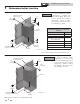

Provide air openings to room:
Boiler alone in boiler room
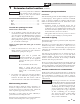
1. No air ventilation openings into the boiler room are
needed when clearances around the Noble Fire Tube
are at least equal to the SERVICE clearances shown in
FIG.’s 1-1 and 1-2. For spaces that do NOT supply this
clearance, provide two openings as shown in FIG. 1-1.
Each opening must provide one square inch free area
per 1,000 Btu/hr of boiler input.
Boiler in same space with other gas or oil-fired
appliances
1. Follow the National Fuel Gas Code (U.S.) or CSA
B149.1 (Canada) to size/verify size of the combustion/
ventilation air openings into the space.
The space must be provided with
combustion/ventilation air openings
correctly sized for all other appliances
located in the same space as the Noble
Fire Tube.
Do not install the boiler in an attic.
Failure to comply with the above
warnings could result in severe personal
injury, death, or substantial property
damage.
2. Size openings only on the basis of the other appliances
in the space. No additional air opening free area is
needed for the Noble Fire Tube because it takes its
combustion air from outside (direct vent installation).
Wall mounting location
Ensure the wall for which the boiler is intended to be
mounted is comprised of either, cement, brick, block, or
wooden studs spaced 16" apart from center. Ensure the
wall is capable of supporting at least 200 pounds.
If flooding is possible, elevate the boiler sufficiently to
prevent water from reaching the boiler.
Ensure the boiler is installed in a location that minimizes
the risk of water damage due to valves, pumps, etc.
Residential garage installation
Precautions
Take the following precautions when installing the appliance in
a residential garage. If the appliance is located in a residential
garage, it should be installed in compliance with the latest
edition of the National Fuel Gas Code, ANSI Z223.1 and/or
CAN/CGA-B149 Installation Code.
• Appliances located in residential garages and in
adjacent spaces that open to the garage and are not part
of the living space of a dwelling shall be installed so that
all burners and burner ignition devices are located not
less than 18 inches (46 cm) above the floor.
• The appliance shall be located or protected so that it is
not subject to physical damage by a moving vehicle.
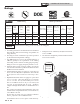
Vent and air piping
The Noble Fire Tube requires a special vent system, designed for
pressurized venting.
The boiler is to be used for either direct vent installation or for
installation using indoor combustion air. When room air is
considered, see Section 3, General Venting. Note prevention of
combustion air contamination below when considering vent/
air termination.
Vent and air must terminate near one another and may be
vented vertically through the roof or out a side wall, unless
otherwise specified. You may use any of the vent/air piping
methods covered in this manual. Do not attempt to install the
Noble Fire Tube using any other means.
Be sure to locate the boiler such that the vent and air piping can
be routed through the building and properly terminated. The
vent/air piping lengths, routing and termination method must
all comply with the methods and limits given in this manual.
Prevent combustion air contamination
Install air inlet piping for the Noble Fire Tube as described in
this manual. Do not terminate vent/air in locations that can
allow contamination of combustion air. Refer to Table 1A,
page 10 for products and areas which may cause contaminated
combustion air.
You must pipe combustion air to the boiler
air intake. Ensure that the combustion air will
not contain any of the contaminants in Table
1A, page 10. Contaminated combustion air
will damage the boiler, resulting in possible
severe personal injury, death or substantial
property damage. Do not pipe combustion
air near a swimming pool, for example.
Also, avoid areas subject to exhaust fumes
from laundry facilities. These areas will
always contain contaminants.
⚠WARNING
⚠WARNING
1 Determine boiler location (continued)
9
Installation & Service Manual
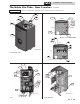
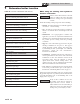
Recommended clearances for service access
- Front ............................................................................. 24"
- Left ................................................................................ 12"
- Right ............................................................................. 12"
- Bottom .......................................................................... 24"
If you do not provide the recommended
service clearances shown, it may not be
possible to service the boiler without
removing it from the space.
NOTICE
FIRE TUBE
™