SYNC - PCP Rev A PC PROGRAM INSTRUCTIONS FOR THE SYNC Models: 1.0 -- 1.3 -- 1.5 WARNING This manual must only be used by a qualified heating installer / service technician. Read all instructions, including this manual, the SYNC Installation and Operation Manual, and the SYNC Service Manual, before installing. Perform steps in the order given. Failure to comply could result in severe personal injury, death, or substantial property damage. Save this manual for future reference.
Contents 1. INSTALLATION 6. PARAMETERS Program Installation ..................................................... 3 Parameter Information Screens ...................................10 USB Installation............................................................ 3 Changeable Parameters ..............................................11 Program Setup ............................................................. 3 Set 1: System Setup ....................................................
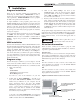
PC Program Instructions 1 Installation Program installation There are two programs available for programming and monitoring the SYNC boilers. SITECS937Lab is used to monitor the operation of the boiler and program a few displayrelated parameters. SMART TOUCH PC is used to program the bulk of the parameters in the controls. To begin installation of the programs, please insert your SMART SYSTEM CD into the CD drive. If you have Autostart enabled, the SMART SYSTEM software screen will load.
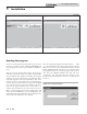
PC Program Instructions 1 Installation Figure 1-1 SMART TOUCH PC Main Screen Figure 1-2 Sitecs937Lab Main Screen Starting the program To start one of the programs, double-click on the icon (if you put it on your desktop), or click on Start, then Programs, and select the program you wish to start. See FIG 1-1 and FIG 1-2 above. There are two access levels for this program. The user access level allows only certain settings to be changed. The installer access level allows more settings to be changed.
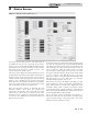
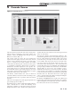
PC Program Instructions 2 Status Screen Figure 2-1 SMART TOUCH Status Screen To monitor and record the operation of the heater, click on the Status tab along the top of the Main Screen window (FIG. 1-1, page 4). When using the SITECS937Lab program, you will need to choose which controller you wish to monitor. The Status Screen will appear (see FIG. 2-1 above). The screen is divided into several sections.
PC Program Instructions 2 Status Screen Figure 2-1 continued. . . At the top right of the window is the Fan Speed status information. Included in the Fan Speed status are Min., Max., and Ignition fan speeds. If Ramp Delay is activated, the Ramp Delay limit is shown. The target and actual fan speeds are displayed, and if the actual speed is within acceptable limits.
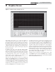
PC Program Instructions 3 Graphics Screen Figure 3-1 SMART TOUCH Graphics Screen The Graphics Screen allows you to observe the changes in various readings while the heater operates (see FIG. 3-1). Note that the vertical scale has two numbers for each division.
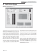
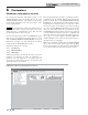
PC Program Instructions 4 Fault History Screen Figure 4-1 Fault History Screen The Fault History Screen provides historical data about the operation of the SMART TOUCH controls.. Click on the Fault history button along the top of the Main Screen window (FIG. 1-1), and then click on Read from Control in the pull-down menu. After uploading data from the selected program, a window will appear with the status of numerous counters and lists of the most recent events (see FIG. 4-1 above).
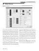
PC Program Instructions 5 Cascade Screen Figure 5-1 Cascade Screen The Cascade Screen provides the status of the cascade system. The PC must be connected to the Leader (address 0-1) appliance. Click on the Cascade button along the top of the Main Screen window (FIG. 1-1). The Cascade System area shows the power demand and setpoint, the boiler pump status, the boiler status, and the priority of each controller in the cascade.
PC Program Instructions 6 Parameters Parameter information screens By accessing the Parameter Information Screens on the SMART TOUCH program, the installer can view all of the SMART TOUCH parameters. The installer can also change certain specific parameters to fine tune the operation of the boiler to the installation. NOTE The PC cable must be connected to either the PC1 or PC2 connection. When connected, the status screen on the SYNC will show a communication error.
PC Program Instructions 6 Parameters (continued) Changeable parameters Figure 6-2 Parameter Set 1D The following is a brief discussion of the changeable parameters, their default settings, the range of adjustment, and their location. The title for the parameters may differ slightly from the PC to the boiler display. To prevent confusion, the boiler display version will be listed in parenthesis. Set 1: System setup Set 1 is accessed by clicking on Parameters at the top of the Main Screen window (FIG.
PC Program Instructions 6 Parameters Set 2: Functional Data Set 2 is accessed by clicking on Parameters at the top of the Main Screen window, then clicking on Set 2: Functional Data on the pull-down menu (FIG. 6-1, page 10). Cascade control Parameters 2DJ and 2DK determine the time delays used by the Cascade. To access the Cascade parameters, click on the tab labeled 2D Cascade.
PC Program Instructions 6 Parameters (continued) Figure 6-5 Parameter Set 2E Figure 6-6 Parameter Set 4A Parameter 2EB sets the pump delay time for the boiler pump after an over-temperature condition. This time is adjustable from 0 minutes to 40 minutes. The default time is 2 minutes. Space Heating (SH) user setpoint (User Setp) If the boiler pump or HW pump have not been active in a 24 hour period, the SMART TOUCH will activate the appropriate pump for a programmed time to prevent jamming.
PC Program Instructions 6 Parameters SH off-on differential (SH off/on df) Night setback temperature (NSB Setp) The SH Off-on Differential sets how many degrees below the turn-off temperature the outlet temperature has to go before the boiler will turn on. This parameter can be changed by accessing parameter 4AE. The temperature range of this parameter is 0°F to 86°F. The default value is 20°F.
PC Program Instructions 6 Parameters (continued) Tank differential temp Cascade max SH step power based (Max outl temp) This parameter determines how far below the tank setpoint the tank sensor temperature must go to start a HW call for heat. This setting can be adjusted by accessing parameter 4AT. The temperature range is 0°F (0°C) to 100°F (38°C). The default value is 5°F (3.5°C).
PC Program Instructions 6 Parameters Cascade SH pump delay after SH demand (Boiler Pump D) Each burner control in the Cascade must be given a unique address. This address can be changed by accessing parameter 4CC. The Leader (top) burner (to which the thermostat/zone control, system sensor, and system pump (if controlled by the boiler) are connected) must be set to address 0. All the Member burners must be given an address from 1 to 15. The range of this parameter is 0 to 15. The default value is 0-1.
PC Program Instructions 6 Parameters (continued) No. of months for service reminder (Serv Not time) When the boiler control determines that a scheduled service is due based on days of installation, the boiler display will show a “Maintenance Required” screen. This parameter is adjustable by accessing parameter 4EA. The time range for this parameter is 0 months to 36 months. The default time is 12 months.
PC Program Instructions 6 Parameters Figure 6-11 Outdoor Air Reset Curve BMS Setpoint at min voltage (BMS setpt min V) If parameter 4CB is set to 2, the control must know what minimum setpoint temperature to use. This can be changed by accessing parameter 4GA. The temperature range for this parameter is 32°F (0°C) to 248°F (120°C). The default value is 70°F (21°C). BMS Setpoint at max voltage (BMS setpt max V) If parameter 4CB is set to 2, the control must know what maximum setpoint temperature to use.
PC Program Instructions 6 Parameters (continued) BMS Voltage at min power (BMS V @min mod) Figure 6-13 Save Parameter File Window If parameter 4CB is set to 0, the control must know what voltage corresponds to the minimum power. This can be changed by accessing parameter 4GI. The range for this parameter is 0Vdc to 4GJ The default value is 2Vdc. BMS Voltage at max power (BMS V @max mod) If parameter 4CB is set to 0, the control must know what voltage corresponds to the maximum power.
Revision Notes: Revision A initial release.