WA-SER_100161799_2000019082_Rev D Service Manual Models: 125 - 200 WARNING This manual must only be used by a qualified heating installer / service technician. Read all instructions, including this manual and the Armor Wall Mount Installation and Operation Manual, before installing. Perform steps in the order given. Failure to comply could result in severe personal injury, death, or substantial property damage. Save this manual for future reference.
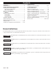
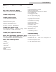
Contents CONTENTS........................................................................ 2 Hazard Definitions .............................................................. 2 PLEASE READ BEFORE PROCEEDING ........................ 3 Handling Ceramic Fiber Materials ...................................... 3 When servicing water heater ........................................ 3 Water heater operation ................................................ 3 WHAT IS IN THIS MANUAL .....................................
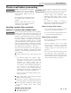
Service Manual Please read before proceeding WARNING Installer – Read all instructions, including this manual and the Armor Wall Mount Installation and Operation Manual, before installing. Perform steps in the order given. NOTICE Have this water heater serviced/inspected by a qualified service technician at least annually. Failure to comply with the above could result in severe personal injury, death or substantial property damage.
Service Manual What is in this manual? Service The Armor wall mount display • Display panel readout, buttons and their functions Control module inputs • Control module inputs and options Control module outputs • Control module outputs and options General • How the water heater operates • How the control module operates • Access modes -- user and installer • Sequence of operation -- Water Heating Control panel menu access • Accessing programming mode and locating menus (See separate guide covering the P
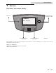
Service Manual 1 Service The Armor wall mount display NAVIGATION DIAL (PRESS OR TURN) RESET KEY STANDBY TANK: 125°F (130) MENU SETPOINTS LEFT SELECTED KEY (SOFT KEY) SHDN RIGHT SELECTED KEY (SOFT KEY) IMG00459 The information on the bottom of the display shows the functions of the two SELECT keys (on either corner), and the NAVIGATION dial (in the center): MENU = Left SELECT Key SETPOINTS = NAVIGATION Dial - Pressing Down SHDN = Right SELECT Key 5
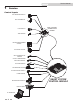
Service Manual 1 Service Control inputs GAS PRESSURE SWITCH DHW THERMOSTAT LOW VOLTAGE CONNECTION BOARD FLOW SWITCH TANK SENSOR BUILDING MANAGEMENT SYSTEM LOW WATER CUTOFF INLET TEMPERATURE SENSOR OUTLET TEMPERATURE / HIGH LIMIT SENSOR FLUE GAS SENSOR AIR PRESSURE SWITCH LOUVER PROVING SWITCH FLAME SENSOR SMART SYSTEM CONTROL MODULE BLOCKED DRAIN SWITCH DISPLAY PANEL PC INTERFACE 6 MENU SETPOINTS SHDN
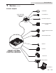
Service Manual 1 Service (continued) Control outputs ALARM BELL LOW VOLTAGE CONNECTION BOARD LOUVER RELAY RUN TIME CONTACTS BUILDING MANAGEMENT SYSTEM BUILDING RECIRCULATION PUMP WATER HEATER PUMP IGNITOR BLOWER SMART SYSTEM CONTROL MODULE GAS VALVE DISPLAY PANEL MENU SETPOINTS SHDN PC INTERFACE 7
Service Manual 1 Service General Operation How the water heater operates The Armor wall mount water heater uses an advanced stainless steel heat exchanger and an electronic control module that allows fully condensing operation. The blower pulls in gas and air and pushes flue products out of the water heater through the heat exchanger and flue piping. The control module regulates blower speed to control water heater firing rate.
Service Manual 1 Service (continued) Table 1A Sequence of operation OPERATION DISPLAY 1. The control will turn on the water heater pump (always ON except in Night Setback). The flow switch and/or LWCO must close. 2. The control turns on power to the louver relay. The louver proving switch, air pressure switch, and blocked drain switch must close. 3. The control starts the prepurge cycle. 4. The control starts the trial for ignition by firing the spark electrode and opening the gas valve. 5.
Service Manual 1 Service Display panel menu access Table 1B Use this procedure to access menus from the display panel BUTTON SCREEN STATUS [SHDN] [YES] [MENU] OPERATION Press the RIGHT SELECT soft key [SHDN]. Press the LEFT SELECT soft key [YES]. Press and hold the LEFT SELECT soft key [MENU] for five (5) seconds. Rotate the NAVIGATION dial clockwise until 5 is displayed (first digit on the left). Press the NAVIGATION dial to select the next digit.
Service Manual 1 Service (continued) Display panel parameter access Table 1C This is a typical example of accessing a parameter, shown for parameter DHW Settings, TANK MIN Setpt BUTTON SCREEN STATUS OPERATION DISPLAY This example shows how to access parameter Temperature Settings. The first display shown is at the beginning of the menu listings, after entering the installer access code. Rotate the NAVIGATION dial counterclockwise until the arrow (>) is next to DHW SETTINGS.
Service Manual 1 Service Parameter table Table 1D This table lists SMART SYSTEM control module parameters and where to access them ANTICYCLING DHW SETTINGS FUNCTIONS DATA LOGGING GENERAL Menu 12 Description User Access See Page Display Modify Installer Access Display Modify Time and Date 14 Yes Yes Yes Yes Software Version (read only) 14 No No Yes No Temperature Units (ºC/ºF) 14 Yes Yes Yes Yes DHW Night Setback Offset 14 No No Yes Yes DHW Night Setback On Times 14 N
Service Manual 1 Service (continued) Parameter table Table 1D (continued from previous page) This table lists SMART SYSTEM control module parameters and where to access them SERVICE NOTIFICATION BMS CIRCULATION PUMPS CONTROL MODES Menu Description User Access See Page Display Modify Installer Access Display Modify BMS Tstat Input 16 No No Yes Yes BMS 16 No No Yes Yes ModBus 16 No No Yes Yes ModBus T/O 16 No No Yes Yes Cascade Address 16 No No Yes Yes Cascade Type
Service Manual 1 Service Viewable and changeable control parameters CAUTION Before changing parameters, note the settings so that the unit can be returned to its original operating parameters. General Time and Date The control uses an internal clock for the night setback feature and for logging of events. For these features to work correctly, the clock must be set when the water heater is first installed or anytime the water heater has been powered off for more than four (4) hours.
Service Manual 1 Service (continued) To save any changes and return to the Home Screen, press the Freeze Protection Burner Differential RIGHT SELECT [HOME] key. To return to the Status Screen Once the burner has started firing due to a low inlet temperature, without saving the changes, press the LEFT SELECT [EXIT] key. the inlet temperature must increase by this amount before the burner turns back off.
Service Manual 1 Service Anti-Cycling Anti-Cycling Time Once a DHW demand has been satisfied, a set amount of time must elapse before the control will respond to a new DHW demand. The control will block the new heat demand and anticycling will be shown in the display until the time has elapsed or the water temperature drops below the Anti-Cycling Override Differential parameter. This parameter can be changed by the installer by accessing the Anti-Cycling Time parameter.
Service Manual 1 Service (continued) Maximum Cascade Set Point This parameter determines the set point used by the individual water heaters in a Cascade. When a water heater is commanded to fire by the Leader water heater, it will attempt to achieve this temperature at its outlet. The Leader water heater will limit the modulation of the last water heater to fire in order to hold the temperature at the tank sensor to the user set point.
Service Manual 1 Service Rate at Maximum Volts When programmed for BMS control through the 0 - 10V BMS input or through ModBus and the BMS Type is programmed as POWER, the modulation percentage represented by the Volts at Maximum parameter is set by the Rate at Maximum Volts parameter. When used with a Cascade, this percentage applies to the total output of the Cascade. The minimum value is the Rate at Minimum Volts setting and the maximum is 100%. The default value is 100%.
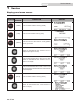
Service Manual 2 Maintenance Maintenance and annual startup Table 2A Service and Maintenance Schedules Service technician (see the following pages for instructions) Owner maintenance General: • Address reported problems • Inspect interior; clean and vacuum if necessary; • Clean condensate trap and fill with fresh water • Check water heater area Daily • Check pressure/temperature gauge ANNUAL START-UP • Check for leaks (water, gas, flue, condensate) • Verify flue and air lines in good condition a
Service Manual 2 Maintenance WARNING Follow the service and maintenance procedures given throughout this manual and in component literature shipped with the water heater. Failure to perform the service and maintenance could result in damage to the water heater or system. Failure to follow the directions in this manual and component literature could result in severe personal injury, death, or substantial property damage.
Service Manual 2 Maintenance (continued) Flue vent system and air piping 1. Visually inspect the entire flue gas venting system and air piping for blockage, deterioration or leakage. Repair any joints that show signs of leakage. Verify that air inlet pipe is connected and properly sealed. 2. Verify that water heater vent discharge and air intake are clean and free of obstructions.
Service Manual 2 Maintenance Inspect ignition and flame sense Check burner flame electrodes 1. Remove the ignition and flame sense electrodes from the water heater heat exchanger access cover. 1. Inspect flame through observation window. 2. If the flame is unsatisfactory at either high fire or low fire, turn off water heater and allow water heater to cool down. Remove the burner and clean it thoroughly using a vacuum cleaner or compressed air.
Service Manual 2 Maintenance (continued) Cleaning heat exchanger For recommended materials; including brush, appropriate extension(s), refractory cover, and detailed instructions see Table 2B - Heat Exchanger Cleaning Kits. 1. Shut down water heater: • Follow the “To Turn Off Gas to Appliance” instructions for the water heater in Section 10 Startup of the Installation and Operation Manual. • Do not drain the water heater unless it will be exposed to freezing temperatures.
Service Manual 3 Troubleshooting Label all wires prior to disconnection when servicing controls. Wiring errors can cause improper and dangerous operation. Always disconnect power to the water heater before servicing. Failure to comply could result in severe personal injury, death, or substantial property damage. Never jumper (bypass) any device WARNING except for momentary testing as outlined in the Troubleshooting chart. Severe personal injury, death, or substantial property damage can result.
Service Manual 3 Troubleshooting (continued) Table 3A Troubleshooting Chart - No Display FAULT CAUSE CORRECTIVE ACTION • Check external line switch, fuse, or breaker. • Check position of ON/OFF switch. Turn switch to the ON position. - No 120 VAC supplied to unit. • Check 120 VAC through the ON/OFF switch. • Check wiring harness connection between display board and main control board. Connect harness at both points. No Display - No voltage through the switch. • Replace switch.
Service Manual 3 Troubleshooting Checking temperature sensors The water heater temperature sensors (inlet water, outlet water, system water, and flue) are all resistance type devices. The following tables show the correct values for the sensors at various temperatures. Use an ohmmeter to read the resistance of the sensor at a known temperature. If the resistance of the sensor does not closely match its corresponding table, replace the sensor.
Service Manual 3 Troubleshooting (continued) Table 3E Troubleshooting Chart - Noisy System FAULT CAUSE CORRECTIVE ACTION - Supply gas problem. Natural gas pressures • Refer to Section 7 - Gas Connections of the Armor should be between 4 inches w.c. and 14 Wall Mount Installation and Operation Manual for detailed inches w.c. LP gas pressures should be information concerning the gas supply. between 8 inches w.c. and 14 inches w.c. - Gas/air mixture problem.
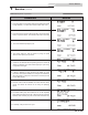
Service Manual 3 Troubleshooting Table 3F Troubleshooting Chart - Fault Messages Displayed on Water Heater Interface FAULT DESCRIPTION CORRECTIVE ACTION • Check water heater pump operation on a call for heat. Flow Switch (will require a manual reset once condition has The flow switch is not making. been corrected. Press the RESET button on the SMART SYSTEM display to reset.) Blown fuse.
Service Manual 3 Troubleshooting (continued) Table 3F (continued from previous page) Troubleshooting Chart - Fault Messages Displayed on Water Heater Interface FAULT Anti-cycling DESCRIPTION CORRECTIVE ACTION The main control board has received a call for heat too quickly after the previous call for heat has ended. • The control board will release the call for heat after a set time period. The unit has failed to prove main burner ignition after four (4) attempts.
Service Manual 3 Troubleshooting Table 3F (continued from previous page) Troubleshooting Chart - Fault Messages Displayed on Water Heater Interface FAULT DESCRIPTION CORRECTIVE ACTION The unit was running and lost the flame signal. This condition occurred four (4) straight times. • Check wiring harness connection at the gas valve and at the main control board. • Inspect spark electrode and associated wiring for damage and connection.
Service Manual 3 Troubleshooting (continued) Table 3F (continued from previous page) Troubleshooting Chart - Fault Messages Displayed on Water Heater Interface FAULT DESCRIPTION Flame Sequence CORRECTIVE ACTION • Check supply voltage for proper polarity. (will require a manual reset once the condition The flame detector circuit is seeing a flame has been corrected. Press signal while no flame is present. the RESET button on the SMART SYSTEM display to reset.
Service Manual 3 Troubleshooting Table 3F (continued from previous page) Troubleshooting Chart - Fault Messages Displayed on Water Heater Interface FAULT DESCRIPTION CORRECTIVE ACTION • Vent/air intake lengths exceed the maximum allowed lengths. Refer to Section 3 - General Venting of the Armor Wall Mount Installation and Operation Manual for proper lengths.
Service Manual 3 Troubleshooting (continued) Table 3F (continued from previous page) Troubleshooting Chart - Fault Messages Displayed on Water Heater Interface FAULT DESCRIPTION Sensor Shorted (will require a manual reset once the condition Either the inlet water or outlet water has been corrected. Press temperature sensor has been shorted. the RESET button on the SMART SYSTEM display to reset.) Louver Proving CORRECTIVE ACTION • Check the sensors and their associated wiring.
Service Manual 3 Troubleshooting Table 3F (continued from previous page) Troubleshooting Chart - Fault Messages Displayed on Water Heater Interface FAULT DESCRIPTION CORRECTIVE ACTION • Verify that the system is full of water and that all air has been properly purged from the system. Outlet Temp High Outlet water temperature has exceeded the maximum outlet water temperature. • Verify that the water heater is piped properly into the system.
Service Manual 3 Troubleshooting (continued) Table 3F (continued from previous page) Troubleshooting Chart - Fault Messages Displayed on Water Heater Interface FAULT DESCRIPTION 120 VAC input to the main control board has dropped below 80 VAC. Low 24 VAC CORRECTIVE ACTION • Check 120 VAC supply to the transformer. • Check wiring connections at the low voltage terminal strip. • Check the wire size/length to remote devices. • Replace the transformer.
Service Manual 3 Troubleshooting Combustion Analysis Procedure Table 3G Flue Products 1. Remove the flue temperature sensor from the flue pipe connection. Note: Combustion measurements will be made at this point. Natural Gas 2. If the water heater is OFF, place the water heater into the active position by pressing the RIGHT SELECT [ON] key (see page 5). 3. Locate the pinhole button below the RESET button on the display board (see page 5).
Service Manual 3 Troubleshooting (continued) Gas valve adjustment procedure If adjustment of the gas valve is deemed necessary, use the following procedure: Locate the throttle adjustment screw on the side of the venturi valve (FIG. 3-2). Using a screwdriver, turn the screw a 1/4 turn counterclockwise to increase CO2 levels or a 1/4 turn clockwise to decrease CO2 levels.
Notes 38
Notes 39
Revision Notes: Revision A (ECO #C11832) initial release. Revision B (PCP #3000010953 / CN #100010523) reflects an update to Table 2A on page 19 and Table 2C on page 23. Revision C (PCP #3000029323 / CN #500018870) reflects a change from “minimum” to “typical” flow rate on page 27. Revision D (PCP #3000030779 / CN #500020179) reflects an update to Table 2A.