
Installation & Assembly
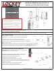

Step 5: Verify Correct Spindle Length
With the Deadlatch installed, hold the Inside Body (#2) and Rubber Trim Plate (#3) to the door.
Place Spindle (#5) through Latch, into the Inside Body, as far as possible.
Spindle should extend from exterior of door 3/8” min. to 5/8” max.
If Spindle is too long, cut it to the correct length using pliers.
*IMPORTANT:
If spindle extends less than 3/8” it may not engage the lock.
If spindle extends more than 5/8”, it will cause the lock to bind.
Step 6: Complete Installaon
Place the Rubber Trim Plate (#3) on the backside of the Outside Body (#1).
Place the Outside Body on the door.
The Hex Bolts (#8) should extend into the top and boom holes.
The Support Pin (#11) should extend through the hole in the Latch (#4).
Insert the Spindle (#5) into the Outside Body (#1) ensuring it’s in the proper angled posion.
*IMPORTANT: SPINDLE POSITION/ANGLE
RIGHT-HAND DOORS: From inside, place spindle through Latch, into the Outside Body in the 2:00/8:00 posion (above).
LEFT-HAND DOORS: From inside, place spindle through Latch, into the Outside Body in the 10:00/4:00 posion (below).
Place the Rubber Trim Plate (#3) and Inside Body (#2) on the inside of the door.
Using a screwdriver, secure the lock to the door (screw length dependent on door thickness).
Test the operaon of the latch by turning the inside thumbturn.
Locate posion where latch strikes door frame and install Strike Plate (#7).
TEST YOUR LOCK: Press ‘C’ buon (clear), followed by your combinaon. Turn knob and lock will open.
Aer installing and tesng the lock, secure Faceplate (#6).
Note: If latch scks, first make sure Support Pin is in place. Second, verify correct spindle length (see step 5).
= 3/8” to 5/8”
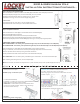
6. Replace the cover plate and secure with four (4) Red Screws,
using a #2 screwdriver.
7. TEST CODE before installing/re-installing lock.
3. PRESS & HOLD ‘C’ BUTTON to release tumblers.
IMPORTANT: ‘C’ buon MUST be pressed and held down when
removing and inserng tumblers. Failure to do so will damage
the lock and void the warranty.
WARNING:
Do NOT force tumblers into posion!
4. While holding the ‘C’ BUTTON, remove/add CODE (Red) and
NONCODE (Blue) tumblers to create your desired code.
Ex: 3 Red = 3-Digit Code / 6 Red = 6-Digit Code
5. Aer changing your code, release the ‘C’ BUTTON to secure the
tumblers in place.
How to Change User Code/Combinaon
SAVE
1. Using a #2 screwdriver, remove the four (4) Red Screws.
2. Carefully remove cover plate.
WARNING: Springs are aached to plate.
‘C’ = CLEAR (DO NOT REMOVE)
‘Y’ = PASSAGE (‘Y’ Tumbler may be removed to disable PASSAGE FUNCTION)
For more helpful ps and installaon instrucons, visit www.LOCKEYUSA.com
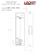
2930 & 2945 Narrow Stile
Installation Instructions Continued...