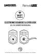
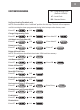
® ELECTRONIC DEADBOLT & LEVER LOCK LS-5i USER MANUAL 1 6 2 3 7 8 4 9 5 0 1 6 2 3 4 5 7 8 9 0 ATTENTION: Please do not use an “electronic screwdriver” for installation
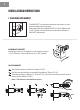
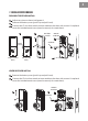
1 INSTALLATIONS INSTRUCTIONS 1. CONFIGURE LATCH BACKSET The BACKSET is the distance between the center of cross bore and edge bore of the door. Adjustable latch fits both BACKSET of 2-3/8” (60mm) and 2-3/4” (70mm). Please follow the steps shown below for BACKSET adjustment. DEADBOLT BACKSET Rotate the latch case as diagram on the right for backset 2-3/4” (70mm) or reverse direction for 2-3/8” (60mm). LEVER BACKSET A The backset shown on the left is 60mm (2-3/8”).
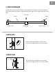
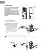
2 2. IDENTIFY DOOR HANDING Face the door from outside, the door is left-handed if the hinge is on the left-hand side of the door, whereas the door is right-handed if the hinge is on the right-hand side of the door. DOOR (Left-handed) INTERIOR EXTERIOR HINGE (Right-handed) 3. INSTALL LATCH Insert the latch and tighten it with screws. Please use “tapping screws” for metal doors. 4. INSTALL STRIKE Insert the strike and tighten it with screws. Please use “tapping screws” for metal frames.
3 5. INSTALL KEYPAD ASSEMBLY DEADBOLT KEYPAD ASSEMBLY A Ensure the latch bolt is retracted. B Please refer to diagram B for cylinder installation. Place deadbolt against keypad with tailpiece in horizontal position inserted through hub of the latch. C B B C IC WIRE Pass the IC wire under the latch to the interior side of the door. LEVER KEYPAD ASSEMBLY A A Place the leverset against keypad with tailpiece in vertical position inserted through cam of the latch.
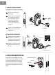
4 7. INSTALL RECEIVER MODULE DEADBOLT RECEIVER INSTALL A Adjust turn piece as shown in diagram A. B Remove the battery cover (push it up and pull it out). C Connect the IC wire then attach receiver module to the door with screws. It’s optional to use the included wood screw (wood screw only for wood doors). A B WOOD SCREWS C SCREWS TURN PIECE (Right Handed Door) BATTERY COVER (Left Handed Door) LEVER RECEIVER INSTALL A Remove the battery cover (push it up and pull it out).
5 8. INSTALL BATTERIES Insert 4 AA Alkaline or Lithium batteries and put the battery cover back on the receiver module. Do not use rechargeable (NiCD, NiHM, LiPo, etc.) batteries or batteries with a voltage rating of under/over 1.5v * Please Note: Deadbolt model will not function until door handing is programmed on the lock (pg.8) BATTERY COVER 9. CHANGE LEVER HANDING A Be sure the levers are unlocked.
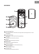
6 LOCK OVERVIEW 6 5 1 2 7 1 2 3 4 5 6 7 8 9 0 8 3 4 1 LOCKSTATE BUTTON The LockState Button is utilized for entering codes and setting functions. It’s also a lock button. 2 NUMBER BUTTONS Input buttons for codes and function programming. 3 CYLINDER Lock/Unlock the lockset from exterior. 4 GASKET Prevent water permeating into lockset. 5 BATTERY LID Slide the lid to change the batteries. 6 BATTERY HOLDER Four AA (1.5v) Alkaline or Lithium batteries only.
7 SPECIFICATIONS/FUNCTIONS Power: 6v, four AA (1.5V) Alkaline or Lithium batteries only. Low battery warnings at 4.25V and 3.75V Programming Code (PC): The preset programming code is 123456. Please change it to a new code for security. Programming code length is 4-10 digits. Local Codes: Codes that are programed using the programming code at the lock. There is a limit of 10 in memory and the code 1234 is programmed by default. Local code lengths are 4-10 digits.
8 FUNCTION PROGRAMMING PC: Programming Code (Default: 123456) LC: Local Code RB: Remote Button Set Door Handing (Deadbolt only) NOTE: Place deadbolt in the “unlocked” position for this step. The lock will not operate until this setting has been programmed during initial setup or after factory reset.
ELECTRONIC DEADBOLT & LEVER LOCK QUICK START GUIDE 1 INSTALL LOCK Refer to pages 1-4 for installation 2 SET DOOR HANDING (DEADBOLT LOCK ONLY) NOTE: Place deadbolt in the “unlocked” position for this step. Lock may not operate until this setting has been programmed during initial setup or after factory reset. Default Programming Code is 123456. 3 WI-FI PROVISIONING Refer to the separate Provisioning Guide for instructions on setting up the lock to connect to your Wi-Fi network for internet access.