EQUIPMENT OPERATION MANUAL Cartesian 200, 300, 400 and 500 Series Features II Variables/ Commands/ Functions Thank you for purchasing the Loctite® Robot. *Read this manual thoroughly in order to properly use this robot. Be sure to read “For Your Safety” before you use the robot. It will protect you from possible dangers during operation. *After having read this manual, keep it in a handy place so that you or the operator can refer to it whenever necessary.
FOR YOUR SAFETY Safety Precautions The precautions stated in this manual are provided for the customer to make the best use of this product safely, and to provide preventive measures against injury to the customer or damage to property. Be sure to follow the instructions Various symbols are used in this manual. Please read the following explanations to understand what each symbol stands for.
FOR YOUR SAFETY CARTESIAN Series Warnings Operators who are involved in the programming, inspection and/or maintenance of this robot must take the “special training course” for industrial robots specified in Article 59 of the Occupational Health and Safety Law and relevant ministry ordinances. Do not leave the unit plugged in (power cord and connectors) when it is not in use for long periods of time. Dust can cause fire. Be sure to shut off the power supply before removing the power cord.
FOR YOUR SAFETY Warnings Check the mounting screws regularly so that they are always firmly tightened. Loose screws may cause injury or defect. Power the unit only with the rated voltage. Excessive voltage can cause fire or malfunction of the unit. Do not sprinkle water or oil on the unit, control box, or its cable. Contact with water can cause electric shock, fire, or malfunction of the unit. IP Protection Rating is IP40.
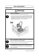
FOR YOUR SAFETY INSTALLATION Warnings Always use a safety barrier. A person entering the robot’s restricted area may be injured. At the entry/exit gate of the safety barrier, install an interlock that triggers an emergency stop when the gate is opened. Ensure there is no other way of entering the restricted area. Furthermore, put up a “No Entry” or “No Operating” warning sign in a clearly visible position.
FOR YOUR SAFETY Warnings Confirm that the unit is properly grounded. Power supply earth should be connected complying with Type D installation. (under 100 Ω of resistance.) Insufficient grounding can cause electric shock, fire, or malfunction of the unit. Plug the power cord into the wall outlet firmly. Incomplete insertion into the wall outlet makes the plug hot and can cause fire. Check that the plug is not covered with dust.
FOR YOUR SAFETY Warnings Be sure to confirm that all the air tubes are connected correctly and firmly. Use the robot in an environment between 0 to 40 degrees centigrade with a humidity of 20 to 95 percent without condensation. Failure to do so may result in malfunction. IP Protection Rating is “IP40.” Use the robot in an environment where no electric noise is present. Failure to do so may result in malfunction or defect. Be sure to secure the movable parts of the robot before transportation.
FOR YOUR SAFETY Warnings Be sure to remove the eye bolt after installing the robot so that it does not hit the arm. Failure to do so may result in injury or breakdown of the unit.
FOR YOUR SAFETY WORKING ENVIRONMENT Warnings When you lubricate or inspect the unit, unplug the power cord from the control box. Failure to do so may result in electric shock or injury. Be sure to shut off the power supply before removing the power cord from the control box. When going inside the safety barrier, place a “Do Not Operate” sign on the start switch. During operation, always have the emergency stop switch within the operator’s reach.
FOR YOUR SAFETY DURING OPERATION Warnings When operations are taking place within the safety barrier, ensure no one enters the robot’s restricted area. If you must go inside the safety barrier, be certain to push the emergency stop switch and put a “Do Not Operate” sign on the start switch. When starting the robot, check that, no one is within the safety barrier and no object will interfere with the robot operating.
FOR YOUR SAFETY CARTESIAN Series Warnings Be sure to check grounding. Improper grounding can cause electric shock or fire. Be sure to use within the voltage range indicated on the unit. Failure to do so may cause electric shock or fire. Plug the power cord into the wall outlet firmly. Failure to do so can cause the input to heat up and may result in fire. Make sure that the power plug is clean. Be sure to unplug the power cord from the wall outlet when you examine or grease the machine.
FOR YOUR SAFETY Warnings Use the machine indoors where no flammable or corrosive gas is present. Emission and accumulation of such gasses could lead to fire. IP Protection Rating is “IP30.” (“IP40” for CE specification) Be sure to unplug the power cord from the wall outlet if the robot will remain unused for long periods of time. Gathered dust could lead to fire. Be sure to use power in the proper voltage range. Failure to do so may result in fire or malfunction.
FOR YOUR SAFETY Cautions Be sure to check grounding. Improper grounding may cause malfunction or defect. Use the Benchtop Robot in an environment between 0 to 40 degrees centigrade with a humidity of 20 to 95 percent without condensation. Failure to do so may result in malfunction. IP Protection Rating is “IP30.” (“IP40” for CE specification) Use the machine in an environment where no electric noise is present. Failure to do so may result in malfunction or defect.
PREFACE The Loctite® Benchtop Robot CARTESIAN Series is a new low cost, high performance robot. We have succeeded in reducing price while maintaining functionality. Energy and space saving is made possible through the combined use of stepping motors and special micro step driving circuits. The Loctite® Robot CARTESIAN Series features diverse applications, high speed, rigidity and precision, and can accommodate a wide variety of requirements. The operation manual consists of the following volumes.
Please be sure to follow the instructions described in these volumes. Proper use of the robot will ensure continued functionality and high performance. The contents described in this volume are based on the standard application. Menu items may vary depending on models. Be sure to shut off the power supply before plugging in the power cord. BE SURE TO MAKE A PROPER GROUNDING WHEN YOU INSTALL THE ROBOT. Be sure to save data whenever it is added or modified.
CONTENTS Features II FOR YOUR SAFETY ______________________________________________________________ i PREFACE ____________________________________________________________________ xiii CONTENTS ____________________________________________________________________xv EXPRESSION STRUCTURE_______________________________________________________ 1 COMMAND LIST ________________________________________________________________ 3 VARIABLE LIST _________________________________________________________________ 8 FUNCTIO
[ ON/OFF Output Control ] ________________________________________________________ 28 Outputting to I/O: set, reset, pulse, invPulse ______________________________________ 28 Outputting after X second: delaySet, delayReset __________________________________ 31 Sounding an alarm buzzer: onoffBZ ____________________________________________ 32 Blinking the LED (Green): onoffGLED __________________________________________ 33 Blinking the LED (Red): onoffRLED ____________________________________________ 34 Outpu
[ Controlling Tool Movement ]______________________________________________________ 68 Moving the Z axis: upZ, downZ, movetoZ________________________________________ 68 Moving straight in CP drive: lineMoveSpeed, lineMoveStopIf_________________________ 70 Executing mechanical initialization by a point job: initMec ___________________________ 72 Position error detection: checkPos _____________________________________________ 73 [ LCD, 7SLED ]_________________________________________________________________ 7
EXPRESSION STRUCTURE Expression An expression is fixed numbers, variables, functions (both of String type and Numeric type) and operators combined. Fixed Number There are 2 types of fixed numbers, Numeric type (e.g.: 125, 2.0,2e15) and String type (e.g.: "ABC".) String type fixed numbers, characters can be specified in hexadecimal code by using “%.” If you want to display “%” on the screen, enter “%%.” e.g.: eoutCOM port2,"%0D%0A" eoutCOM port2,"%%300" outputs CR LF code. outputs %300.
Function Function returns a converted value if values or strings are given. Both built-in functions, which are built-in as robot features, and user definition functions, which can be freely defined, can be used with this robot. User definition functions are defined in the customizing mode. Whether they are Numeric functions or String functions depends on the type of returned values. Operator Operator + * / & = > < >=,=> <=、=< <>,>< == Description Adds the left and right values.
COMMAND LIST If you assign point job data including one of the highlighted ( ) commands to a CP Passing Point, this command will be ignored.
Category Command ld Parameters waitStart Boolean Variable or Expression Boolean Variable or Expression Boolean Variable or Expression Boolean Variable or Expression Boolean Variable or Expression Boolean Variable or Expression Wait Time Read Out Source, Read Out Width Read Out Source, Read Out Width - waitStartBZ - ldi and Condition ani or ori anb orb delay dataIn Delay dataInBCD Pallet Execute Flow Control resPalette incPalette Pallet Number, Destination Number Pallet Number Pallet Number cal
Category Command for for, do-loop next exitFor do loop exitDo upZ donwZ movetoZ Parameters Control Variable, Initial Value, End Value, Step Value Distance, Speed Distance, Speed Distance, Speed Move lineMoveSpeed Speed, Distance or Roatation lineMoveX lineMoveY lineMoveZ lineMoveR X Distance Y Distance Z Distance R Rotation initMec Axis checkPos clrLCD clrLineLCD Rows (1-13) Rows (1-13), Columns (1-40), Character String Rows (1-13), Columns (1-40), Character String Expression outLCD LCD, 7SLE
Category Command outCOM eoutCOM setWTCOM COM Input/Output InCom cmpCOM ecmpCOM clrCOM shiftCOM stopPC startPC declear Variable, Comment, System Control let rem crem setProgNo setSeqNo Z Sensor takeZWadj Parameters Content Port, Character String Outputs a character string from the COM. Port, Character String Outputs the result of an expression from the COM. Expression Sets Wait Time (Period for Time Out) for receiving Port, Wait Time from the COM.
Execute Condition Category Command ld Parameters Boolean Variable or Expression Boolean Variable or Expression Boolean Variable or Expression Boolean Variable or Expression Boolean Variable or Expression Boolean Variable or Expression - ldi and Condition ani or ori anb orb Content ON input OFF input Serial ON input Serial OFF input Parallel ON input Parallel OFF input Blocks serial connection Blocks parallel connection Sequencer Category Command ld ldi Condition and ani or ori Coil Cnnection out
VARIABLE LIST Built-in variables, which are built-in as robot functions, and user definition variables, which can be freely defined, can be used with this robot. User definition variables, except local variables (variables effective only in defined point job data which are defined by the “declear” command), are defined in the customizing mode. (Refer to the operation manual “Features IV” for a description of the customizing mode.) Boolean type 1 bit variable (Holds only a value of 1 (true) or 0 (false).
[Variables] Category Type Sequencer program boo num boo num Current point coordinates Given point coordinates num num num num num num num num num num Given program Given point coordinates num num num num num Description Set to 1 when #seqTCount #seqT(1 to 99) reaches the given value or greater. One counter can count from 0.001 #seqTCount (1 to 50): Integrating Timer to 2,147,483,647 seconds. (0.
FUNCTION LIST Built-in functions, which are built in as robot functions, and user definition functions, which can be freely defined, can be used with this robot. User definition functions are defined in the customizing mode. (Refer to the operation manual “Features IV” for a description of the customizing mode.
x, y: Numeric value or numeric variable n, m: Numeric value made a certain digit or greater by rounding or truncation a, b: String or string variable Category String system Type str num Identifier chr(x) ord(a) num len(a) num strPos(a,b) str strMid(a,n,m) str str(x) str strBin(n,m) str strHex(n,m) str str1SI(x) str str2SIBE(x) str str2SILE(x) str str4SIBE(x) str str4SILE(x) str str4FBE(x) str str4FLE(x) str str8DBE(x) str str8DLE(x) num val(a) num valBin(a) num valHex(
x, y: Numeric value or numeric variable n, m: Numeric value made a certain digit or greater by rounding or truncation a, b: String or string variable Category Type Identifier String system num val2SILE(a) num val4SIBE(a) num val4SILE(a) num val4FBE(a) num val4FLE(a) num val8DBE(a) num val8DLE(a) num valSum(a) num valCRC(a) str str str str bitNot(a) bitAnd(a,b) bitOr(a,b) bitXor(a,b) Features II Description Regards the top 2 characters as a 2 byte signed integer little endian and con
[ Variables ] Free variables: #mv, #mkv, #nv, #nkv, #sv, #skv A “variable” is a container into which a value is placed. This robot has the following variables which can be used freely. When using the following variables, variable declaration is unnecessary.
Input variables:#sysIn1 to 15, #genIn1 to 18, #handIn1 to 4 An input variable is a Boolean variable that can be referenced only. A value cannot be written. The input variables correspond to the I/O-SYS, I/O-1, and I/O-H input pins. When an ON signal is received, the input variable becomes “1” (true).
Output variables: #sysOut1 to 15, #genOut1 to 18, #handOut1 to 4 Output variables are Boolean variables. Output variables corresponds to the I/O-SYS, I/O-1, and I/O-H output pins. When an ON signal is output, the output variables become “1” (true).
Point job starting height : #jobStartHight When a value is assigned (let) to the variable “#jobStartHight” before movement or during movement, the point job starts from an assigned value above the set point Z coordinate. Setting point job data that includes “#jobStartHight” at “point job” is meaningless because the robot has already arrived at the point job start position. Also, since this variable acts only on the set point, the point job start position of the next point does not change. e.g.
Pallet : #palletflag (1 to 100), #palletCount (1 to 100) #palletCount(1 to 100) is a numeric variable and #palletflag(1 to 100) is a Boolean variable. These variables retain the value of the pallet counter and pallet flag of the “Pallet Routine” under Additional function data (1 (true) when the pallet counter is full). By using this variable, a pallet can be moved to the next point, etc. midway or a given pallet can be skipped.
Point job data set on P1 set #handOut1 Point job data set on P2 if ld #palletCount(3) = 5 or #palletCount(3) = 11 else reset #handOut1 endIf loopPalette 3,1 Features II Pick up workpiece. If #palletCount (3) is other than 5 (P2-5), 11 (P2-11), Place (release) workpiece. Increase the pallet 3 counter by 1. If the counter becomes full, advance to the next command. (In this case, the point job ends because there is no next command.) If the counter is not full, move to P1.
Workpiece adjustment: #workAdj_X, #workAdj_Y, #workAdj_Z, #workAdj_R, #workAdj_Rotation Numeric variables. These variables hold the adjustment amount and rotation adjustment amount of each axis of the [Workpiece Adjustment] under Additional function data.
Point job data set in P1 declear str hosei inCom hosei,port1,10 #workAdj_X(6) = hosei String type local variable “hosei” declaration. Receive workpiece adjustment from COM1 at “hosei”.
Point coordinates: #point_X,#point_Y,#point_Z, #point_R,#point_TagCode These variables hold the coordinates and tag code value of the running point. “Running point” is the point with point job data containing this variable set. When point job data containing this variable is set to a job before moving, job while moving, or job while CP moving, the current position of the tool center point and the value of this variable are different.
Given point coordinates: #P_X, #P_Y, #P_Z, #P_R, #P_TagCode These variables hold the coordinates and tag code value of a given point in the current program. This variable holds the original coordinates of the point. This value does not change even when [Workpiece Adjustment] and “#jogStartHight” are used.
Given point coordinates in given programs: #prog_P_X, #prog_P_Y, #prog_P_Z, #prog_P_R, #prog_P_TagCode These variables hold the coordinates and tag code value of a given point in a given program. This variable retains the original coordinates of the point. This value does not change even when [Workpiece Adjustment] and “#jogStartHight” are used.
[ Functions ] Robot functions Built-in functions, that are built-in as robot functions, and user definition functions, which can be freely defined, can be used with this robot. User definition functions are defined in the customizing mode. (Refer to operation manual “Features IV” for a description of the customizing mode.) The following can be used as robot system built-in functions.
Arithmetic functions The following can be used as arithmetic built-in functions.
String functions The following can be used as string built-in functions.
x, y: Numeric value or Numeric variable n, m: Numeric value made a certain digit or greater by rounding or truncation a, b: String or string variable Category Type Identifier String system num valBin(a) num valHex(a) num val1SI(a) num val2SIBE(a) num val2SILE(a) num val4SIBE(a) num val4SILE(a) num val4FBE(a) num val4FLE(a) num val8DBE(a) num val8DLE(a) num valSum(a) num valCRC(a) str str str str bitNot(a) bitAnd(a,b) bitOr(a,b) bitXor(a,b) Features II Description Regards a s
[ ON/OFF Output Control ] Outputting to I/O: set, reset, pulse, invPulse This section explains commands to be output to a tool (output to the I/O.) These commands belong to the category [ON/OFF Output Control.
Therefore, Hand Tool OPEN ← #sysOut15 OFF & #sysOut16 ON Hand Tool CLOSE ← #sysOut15 ON & #sysOut16 OFF Below are the output commands to open/close the hand tool. set #sysOut15 reset #sysOut16 #sysOut16 ON output #sysOut15 OFF output Open hand tool. set #sysOut15 reset #sysOut16 #sysOut16 ON output #sysOut15 OFF output Close hand tool. The command [set] continues to output an ON signal unless the command [reset] is received. Below are the output commands to open/close the hand tool using the pulse.
The commands [pulse] and [invPulse] move on to the next command before the pulse stops. In the following example 2 point job data have different results: pulse #genOut1 100 set #genOut1 delay 100 reset #genOut1 set #genOut2 delay 200 reset #genOut2 set #genOut3 ↓ pulse #genOut2 200 set #genOut3 ↓ #genOut1 #genOut1 #genOut2 #genOut2 #genOut3 #genOut3 0.1 sec 0.1 sec 0.2 sec delay 100 = Stand by for 0.1 second in place.
Outputting after X second: delaySet, delayReset The commands “delaySet” and “delayReset” are used to output ON/OFF signals to a specified output destination after a specified period of time. The delay time can be set from 0.001 sec to 9999.999 sec.
Sounding an alarm buzzer: onoffBZ A point job sounds an alarm buzzer. Command Category Command set ON/OFF Output Control reset onoffBZ Parameter Output Destination (BZ) Output Destination (BZ) ON Time, OFF Time Job Sounds an alarm buzzer. Stops an alarm buzzer. Sounds an alarm buzzer off and on. If these commands “set/onoffBZ” are executed, an alarm buzzer continues to sound until the “reset”command is executed. ON Time and OFF Time for the command “onoffBZ” can be set using variables or expressions.
Blinking the LED (Green): onoffGLED The following commands are valid for the CARTESIAN series only. The following explains how to turn ON or blink the LED light on the front body using point job commands. Command Category Command set ON/OFF Output Control reset onoffGLED Parameter Output Destination (GLED) Output Destination (GLED) ON Time, OFF Time Job Turns the LED (Green) ON. Turns the LED (Green) OFF. Blinks the LED (Green.
Blinking the LED (Red): onoffRLED The following commands are valid for the CARTESIAN series only. The following explains how to turn ON or blink the LED light on the front body using point job commands. Command Category Command set ON/OFF Output Control reset onoffRLED Parameter Output Destination (RLED) Output Destination (RLED) ON Time, OFF Time Job Turns the LED (Red) ON. Turns the LED (Red) OFF. Blinks the LED (Red.
Outputting values from I/O: dataOut,dataOutBCD The optional numeric values “0 to 999,999,999” or tag codes can be output to the I/O or the Boolean free variables (#mv(1~99), #mkv(1~99).) Command Category ON/OFF Output Control Command dataOut dataOutBCD Parameter Output Destination Output Destination Output Value Output Value Output Width Output Width Job Outputs values from the I/O. Outputs values in BCD from the I/O.
[ If Branch, Wait Condition ] if Branch: if, then, else, endIf This section explains point job data commands for executing different jobs according to certain conditions. These commands belong to the category [if Branch, Wait Condition.] Command Category if Branch, Wait Condition Command if then else endIf Parameter - Job if Branch Executes the following commands if true. Executes the following commands if false. End of if Branch Be sure to put the commands for the Condition after “if.
Example 2: If #genIn1 and #genIn2 are both Label 1 ON, sound an alarm buzzer and stand by until a start instruction is received. If either #genIn1 or #genIn2 are not ON, advance to the next job. #genIn1 #genIn2 Sound Alarm And Wait Start The commands for Example 2 are shown below. Label 1 if ld #genIn1 and #genIn2 then waitStartBZ jump L1 endIf (A destination mark for jump command) If the following condition is true, advance to then. If false, advance to the next of endIf.
Wait Condition: waitCond,waitCondTime,timeUp,endWait This section explains the point job data commands for waiting until the sensor (connected to #genIn2) comes ON. These commands belong to the category [Wait Condition.] Command Category Command Parameter Wait Condition waitCondTime timeUp endWait waitCond Period for Time Out - Job Waits for conditions for a certain period. Executes when time is up. End of WAIT command Waits for conditions.
[endWait] and [timeUp] cannot be used alone. A period for Time Out of “waitCondTime” can be set using variable and expressions. Example) declear num wtime if ld #genIn3 then wtime = 3000 else wtime = 1000 endIf waitCondTime wtime ld #genIn2 timeUp set #genOut2 waitStartBZ reset #genOut2 endWait Features II Declare the local variable “wtime.” If #genIn3=ON then Assign 3000 to”wtime.” if Assign 1000 to “wtime.” Wait for 3 seconds/1 second until the following conditions are met.
[ Condition ] Condition Settings: ld, ldi, and, ani, or, ori, anb, orb The following describes the condition commands placed after the If Branch, Wait Condition (if, waitCond, waitCondTime) commans. The command category it belongs to is [Condition.
ld: ON input waitCond ld #genIn2 endWait Waits in place until the following condition is met. #genIn2=ON (condition) End of condition line ldi: OFF input waitCond ldi #genIn2 endWait Waits in place until the following condition is met. #genIn2=OFF (condition) End of condition line and: Series ON input waitCond ld #genIn1 and count>=10 endWait Waits in place until the following conditions are met.
anb: Block series connection waitCond ld count>=10 or flag ldi #genIn1 ani #genIn2 anb endWait Waits in place until the following conditions are met. count is 10 or greater Condition 1 or flag is ON #genIn1 is OFF Condition 2 and #genIn2 is OFF Condition 1 is true and condition 2 is also true End of condition line orb: Block parallel connection waitCond ld count>=10 or flag ldi #genIn1 ani #genIn2 orb endWait Waits in place until the following conditions are met.
[ Delay, Data In, Wait Start ] Time Delay: delay This section explains the point job data command for controlling time delay. Command Category Delay, Data In, Wait Start Command delay Parameter Delay Time Job Stand by in place for a specified period of delay time. The command “delay” is invalid at a CP Passing Point and at a point whose Base Type is CP Passing Point. delay :Delay for the specified period of time.
Delay Time can be set using variable or expression instead of values. Example) declear num wtime if ld #genIn1 then wtime = 100 else wtime = 200 endIf set #genOut1 delay wtime reset #genOut1 Features II Declare the local variable “wtime.” If #genIn1=ON then Assign 100 to “wtime.” If not Assign 200 to “wtime.” Output ON signal to #genOut1. Delay for 0.1 sec/0.2 sec. Output OFF signal to #genOut1.
Waiting for a start instruction: waitStart, waitStartBZ This section explains the point job data commands to stop running until a start instruction is received. Command Category Command Delay, Data In, Wait Start Parameter waitStart - waitStartBZ - Job Stands by in place until a start instruction is received. Stands by in place while sounding an alarm buzzer until a start instruction is received.
If using “waitCondTime” “timeUp” … “endWait” or “if” … ”endIf”, command lines are indented. (See below.) waitCondTime 200 ld #genIn2 timeUp set genOut2 if ld #genIn1 then downZ 20,20 waitCondTime 200 ld #genIn4 timeUp waitStartBZ endWait endIf endWait Be sure not to exceed the 9th level of the indent. If point job data including a line with an indent exceeding the 9th level, it will recognize a running error and the message “Error on point job” will be displayed.
Inputting from I/O: dataIn, dataInBCD Read out a value from the I/O or Boolean variable (#mv (1 to 99), #mkv (1 to 99)) and assign it to the specified variable. Command Category Command Variable to dataIn Delay, Data In, assign to Wait Start Variable to dataInBCD assign to BCD = Binary-Coded Decimal Parameter Input Destination Input Destination Input Width Input Width Job Read out numeric data from I/O. Read numeric data in BCD from I/O. Read out width can be set using variables or expressions.
[ Pallet Control ] Pallet Command: loopPallet, resPallet, incPallet There are two methods for updating the pallet counter. One is [Auto Increment], which increases the counter automatically (the arm will proceed to the next position on the pallet), and the other is [Increment by Point Job], which will not increase the counter (that is, the tool unit will not move to the next position on the pallet) unless the point job specifies it.
During the pallet operation [Increment by Point Job], the tool unit can move as shown in the figure on the previous page. The tool unit returns to P1 before it moves to the next position each time. (P1 → P2 (P2-1) → P1 → P2-2 → P1 → P2-3, and so on.) Below are the pallet commands used for [Increment by Point Job.] Command Category Command Parameter loopPallet Pallet Number, go Point Number resPallet incPallet Pallet Number Pallet Number Pallet Job Increase the counter one by one.
Below are the pallet commands for using the command “incPallet (Increase the specified pallet counter by one)” instead of “loopPallet.”
[ Execution Flow Control ] Subroutine call of type setting job: callBase When a point job, etc. is set at a user definition type point created in the customizing mode, the point job, etc. added to the type is not executed. Also, when an additional function is set at user definition type, and a function of the same type but different number is set at the point, the function data number of the function set at the point has priority. e.g.
In these cases, when the “callBase” command is used in the point job data set at a user definition type point, a subroutine of the point job, etc. added to the type can be called. When the “callBase” command is used in point job data 7 of the example, a subroutine of the command string for the “point job” added to the user definition type of point job data 7 is called when a point job of P1 is executed.
Subroutine call of point job data: callJob While a point job is running, different point job data can be called and executed. The point job data is reduced and easier to read if error Operation and other parts common to multiple point jobs are made into one point job data and used by calling it from another point job data. Also, by making a certain command group which was one part of the point job data, one point job data, only that part can be tested.
When the point job data called by “callJob” command contains a “callJob” command, and the nest level exceeds 10, an error (No. 42) is generated. ( ↓ Example of nest level 2) (Command execution flow) callJob callJob Nest level 1 Nest level 2 Point job data number can also be given by expression. Example) declear num ejob waitCondTime 200 ld #genIn1 timeUp if ld #genIn2 then ejob = 9 else ejob = 10 endIf callJob ejob endWait Features II Local variable “ejob” declaration Waits for 0.
End of point job: returnJob When there are complex conditions and operations that correspond to them and there are no more operations in the point job, the point job can be ended by “returnJob” command. Command category Execution flow control Command returnJob Parameters Job Ends a point job. e.g.
Subroutine call of Program: callProg The following explains how to call and execute other programs while running a point job. Command Category Execute Flow Control Command Parameter callProg Program Number Job Call a subroutine of a program specified by number. The command is invalid at the CP Passing Point or a point whose Base Type is CP Passing Point.
Also, Program Number can be set using expressions. Example) declear num eprg waitCondTime 200 ld #genIn1 timeUp if ld #genIn2 then eprg = 9 else eprg = 10 endIf callProg eprg endWait Declare the local variable “eprg.” Wait for 0.2 sec until the following condition is met. #genIn1=ON (Condition) If the conditions are not met within 0.2 sec, If #genIn2=ON then Assign 9 to “eprg.” If not, Assign 10 to “eprg.” Call a subroutine of Program number 9/10.
Example: The subprogram is set to [Absolute.] The tool unit runs on the coordinates of the point data regardless of the position of the called point. It executes the point job at the start in the work home (in the subprogram) at the current point (called point) and then shifts to P1 (SP1.
If you run the program as a subprogram, the tool unit will not return to the work home. If the program is set to “Relative” or “Moving Amount”, the tool unit will also not return to the work home. The tool unit returns to the work home only when the program is set to “Absolute” and executed independently (not “callProg” running.) Registering the program set to “Relative” If you register a point in JOG mode, you have to select “Absolute” regardless of the position data setting.
Calling points: callPoints Call a point string (defined in customizing mode) with identifier to execute it. Command Category Execute Flow Control Command callPoints Parameter Point String Identifier Job Calls a subroutine of the specified point string. The command “callPoints” is invalid at the CP Passing Point or a point whose Base Type is CP Passing Point. Example) The following point job data is set to P1.
Ending a program: endProg The following explains how to end a program (running the operation) at the current point. The arm will not return to the Work Home position. Command Category Execute Flow Control Command endProg Parameter - Job Ends program run at the current point. The command “endProg” is invalid at the CP Passing Point or a point whose Base Type is CP Passing Point.
Assigning the returned value of a function: returnFunc Assign a value of the specified expression as a returned value and end the function. Command Category Execute Flow Control Command Parameter returnFunc Expression Job Assigns a value of the specified expression as a returned value and end the function. The command “returnFunc” cannot be used for point job data. Jopint Job Data outLCD 7,4,radians(x) Function (Identifier: radians) Call a function. returnFunc 0.
Jumping to a specified point: goPoint, goRPoint, goCRPoint The following explains how to jump to a specified point after carring out a point job instead of going to the next point. Command Category Command goPoint Execute Flow goRPoint Control goCRPoint Parameter Job PTP Condition Number, Point Number PTP Condition Number, Relative Point Number PTP Condition Number, Destination selection Jumps to a specified point. Jumps to a specified relative point.
[goPoint PTP3,25]: Jump to Point 25. (Comply with PTP Condition 03.) If you set “0” as the PTP Condition Number, the movement will comply with the PTP Conditions setting in the program data. If you set “o” as the point number, the arm will go to the Work Home position. (Jump to a point specified by number.) [goRPoint PTP3,-4 : Subtract four from the current reference point number and jump to the point with that number. (Comply with PTP Condition 03.
Jumping to a specified command line: jump, Label Command Category Execute Flow Control Command jump Label Parameter Label Number Label Number Job Jumps to a “Label” specified by number. Destination mark to “jump” to. Example: If #genIn2 is ON, the alarm buzzer sounds and stands by until a start signal comes. If #genIn2 is not ON, go to the next job. Label 1 if ld #genIn2 then waitStartBZ jump L1 endIf (Destination mark) If the following condition is true, go to then. If not, go to the next of endIf.
[ For, Do-loop ] For, Do-loop: for, next, exitFor, do, loop, exitDo Command Category Command for for, do-loop next exitFor do loop exitDo Parameter Control Variable, Initial Value, End Value, Step Value - Job Repeats commands from “for” to “next” until the specified variable changes from Initial Value to End value. Exits from “for” sentence. Repeats commands from “do” to “loop.” Exits from “do” sentence. for ~ exitFor ~ next “for” is a command to specify the number of repetitions.
Parameters (the initial value, end value and step value) of the command “for” can be set using variables or expressions. declear num loop declear num ival if ld #genIn1 then loop = 5 else loop = 10 endIf for ival=1 to loop step 1 (contents of repetition) next Declare the local variable “loop.” Declare the local variable “ival.” If #genIn1=ON then Assign 5 to “loop.” If not Assign 10 to “loop.” The initial value of the variable “ival” is 1.
[ Controlling Tool Movement ] Moving the Z axis: upZ, downZ, movetoZ The following explains how to raise/lower the Z axis only by setting a point job. These commands belong to the category [Move.] Command Category Move Command Parameter upZ Distance, Speed downZ Distance, Speed movetoZ Distance, Speed Job Raises only the Z axis by the specified distance. Lowers only the Z axis by the specified distance. Raises or lower the Z axis to the specified Z coordinates (Absolute coordinates.
The distance or speed can be set using variable or expressions. waitCond ld #genIn2 endWait downZ #P_Z(1)-#point_Z,20 Wait in place until the following conditions are met. #genIn2=ON (Condition) End of conditions Lower or raise only the Z axis at the speed of 20 mm/sec by a distance calculated by deducting the Z coordinates of the current point from the Z coordinates of P1. #P_Z(1): Variable which has the Z coordinates of P1 as a value in the current program.
Moving straight in CP drive: lineMoveSpeed, lineMoveStopIf The following explains how to move straight in CP drive using point job data commands. The speed of CP drive and the moving amount of each axis coordinates can be set. You also can end shifting by setting conditions. Command Category Move Command lineMoveSpeed Parameter Speed (CP speed) X Distance Y Distance Z Distance R Rotate Angle Job Moves by the entered distance in CP drive.
Stopping the arm shift due to setting conditions while running. lineMoveSpeed 3 X:20 Y:0 Z:0 R:0 lineMoveStopIf ld #sysIn1 endLineMove callJob11 Condition to stop shifting If #sysIn1 comes ON, the tool unit stops shifting and goes the next command (callJob11) even before the movement in the Z direction does not reach +20. In this case, you can check with the system flag (#sysFlag34) to find out whether it stopped before or after shifting to the specified distance was complete.
Executing mechanical initialization by a point job: initMec The following commands are valid for the CARTESIAN Series only. The following explains how to execute mechanical initialization (executed when the power of the robot is turned ON) using point job commands. Even if a position error occurs, the tool unit returns to the absolute coordinates (x:0, y:0, z:0, r:0) by executing mechanical initialization.
Position error detection: checkPos The following commands are valid for the CARTESIAN Series only. The following explains how to detect a position error using a point job command. If the checkPos command is executed, the tool unit goes to the absolute coordinates (x:0, y:0, z:0, r:0) regardless of where the tool unit is. After position error detection, it goes to the next point. Command Category Move Command checkPos Parameter Job Detects position errors.
[ LCD, 7SLED ] Displaying the specified strings on the teaching pendant: clrLCD, clrLineLCD, outLCD, eoutLCD The following explains how to display/ not display entered items on the teaching pendant LCD. Command Category LCD Control Command clrLCD Parameter None clrLineLCD Rows outLCD Row, Column, Character String eoutLCD Row, Column, Character String Expression Job Clears the LCD display. Clears only the specified line on the LCD display.
Displaying arbitrary numbers on the 7SLED: sys7SLED, out7SLED The following commands are valid for the CARTESIAN Series only. The following explains how to display arbitrary numbers on the 7SLED on the front body using “out7SLED” command. When executing “sys7SLED” command or switching programs, the program number will be displayed again.
[ COM Input/Output ] COM Input/Output: outCOM, eoutCOM, setCOM, cmpCOM, ecmpCOM, clrCOM, shiftCOM Data can be output or input from the COM. Command Command Parameter Category outCOM Port, Character String Port, Character String eoutCOM Expression Variable Name, Port, inCOM Wait Time setWTCOM COM Input/Output cmpCOM Port, Wait Time Port, Character String ecmpCOM Port, Character String Expression clrCOM Port shiftCOM Port, Shift Number Job Outputs a character string from the COM.
COM Input: inCOM A specified number of characters out of data received from the COM is assigned to a variable. If received data exceeds the specified number of characters, characters counted from the top by the specified number are assigned. If received data is less than the specified number of characters, the robot stands by for a time specified in [setWTCOM] and data which has been received is assigned to a variable. If [setWTCOM] is not used, the tool unit stands by for 0.1 sec.
If point job data including this receive cmpCOM(1) comparison command is set at a CP Passing Point, the robot stands by for 0 sec X=1 to receive data. Wait Time for Reciving* Time Out Received Turns sysFlag(5) ON. Specified Receive Character Buffer Xth Character : Xth Character ≠ = X = X+1 >: Turns sysFlag(2) ON. <: Turns sysFlag(4) ON. ≤ X: Specified Number of Character > Turns sysFlag(3) ON.
Setting Wait Time for receiving data from the COM: setWTCOM You can set Wait Time for receiving data using “inCOM” or “cmpCOM” command. If no data is received after a specified time goes by, it will be recognized as Time out. (Turns a system flag ON.) 0.1 sec is set for the defalt wait time. Clearing COM Receive Buffer: clrCOM Receive buffer is a place where received data is stored. Each port has a receive buffer (8 kbyte.
PC Communication: stopPC, startPC Stopping/Starting COM1 communication stopPC, startPC COM1 is normally used to communicate with the PC. If you use COM1 not to communicate with PC (for sending/receiving C&T data) but to connect to devices to control the robot by point job commands, it is necessary to stop PC communication transaction operated by the system. If stopPC command is executed, PC communication does not work until the power is turned OFF or startPC command is executed.
[ Variables, Comments, System Control ] Declaration and assignment of variable: declear, let A variable that is valid only in point job data containing a declaration command and a user function (customizing mode) is known as a “local variable”. A local variable sets the type and identifier at declaration time. The identifier is the name of the variable and type can be selected from either “numeric type” or “string type”. Also, a local variable can be declared as an array of up to 3 dimensions.
Both of the following point job data use the local variable “count”, but since a local variable is a function which is valid only in point job data containing a declaration command, they do not interfere. For example, 0 is assigned to “count” at point job data 24, but the value of “count” used by point job data 05 does not change. The opposite also applies. e.g.) Joint job data 05 declear numeric count count=0 do count=count+1 callJob 24 if ld count>=10 then exitDo endIf loop e.g.
Comment insertion: rem,crem Comments can be added to point job data and sequencer program commands. Command category Variable, comment, system control Command rem crem parameters String String e.g.) if ld #genIn1 rem #genIn1 Obstruction sensor then waitStartBZ Job 1 line comment Comment in the end of a command line If #genIn1 is true, (#genIn1: Obstruction sensor) : Comment line Sounds a buzzer and stands by until start is given. e.g.
Changing a program number using point job: setProgNo The program number being selected can be changed by the point job. It is available in the following cases. If you set a program number by the point job after the power is turned ON, the same program number will always be activated when the power is turned ON. If you set a program number by the point job at the end at the work home, you can switch it to the next program number. This fuction is useful for executing a series of programs in order.
Changing a sequencer program using point job: setSeqNo The sequencer number being selected can be changed using the point job. However, a complicated command cannot be created because the number of commands for sequencer program is 100 steps maximum. Therefore, you need to create some sequencer programs (executed when the power is turned ON, during standby and during operation) separately so that you can switch between the programs using “setSeqNo.
Warranty Henkel Corporation warrants, to the original Buyer for a period of one (1) year from date of delivery, that the Loctite® Equipment or System sold by it is free from defects in material and workmanship. Henkel will, at its option, replace or repair said defective parts. This warranty is subject to the following exceptions and limitations. 1. Purchaser Responsibilities – The Purchaser shall be responsible for: -Maintenance of the equipment as outlined in the Equipment Manual for the product.
Henkel’s warranty herein is in lieu of and excludes all other warranties of Henkel and its affiliated and related companies (hereinafter the “seller companies”), express, implied, statutory, or otherwise created under applicable law including, but not limited to, any warranty or merchantability and/or fitness for a particular purpose of use.
The specifications of the robot or the contents of this manual may be modified without prior notice to improve its quality. No part of this manual may be reproduced in any form, including photocopying, reprinting, or translation to another language, without the prior written consent of LOCTITE®. ©2005, JSMC., Ltd., All rights reserved.