
Owner's manual

90004RX.01E
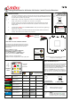
Wiring Instructions for 90 Series & 91 Series 2 and 4 Function Receivers
2
or Disconnect Battery
IDENTIFY POWER
CONNECTION POINT
AND ISOLATE SUPPLY
Fuse
Remove fuse
Vehicle batteries contain gasses
which are flammable and explosive.
Wear eye protection and do not lean
over battery while disconnecting. Do
not wear metal jewellery.
!
WARNING
1
!
BEFORE YOU START
90 02/4 RX
& 91 02/4 RX
have
7 core cable
CONNECT
WIRES
4
Transmitter
Function
Convention
90 00 RX
& 91 00 RX
have
4 core cable
5
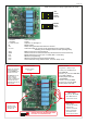
or re-connect Battery
ACTIVATE THE
RECEIVER SUPPLY
Fuse
Replace fuse
Press the Transmitter buttonRESET
to activate the system, and carefully
test each function for correct operation.
7
TEST
6
CONNECT TRANSMITTER BATTERY
Batteries generally have to be
disconnected when shipping.
3
Secure using 5mm (3/16") bolts (not supplied)
through the 4 mounting feet
CAUTION
MOUNT RECEIVER
STOP
POSITIVE
NEGATIVE
!
12/24 Volts DC Nominal
Positive Supply
RED
Negative
BLACK
GREEN
YELLOW
BROWN
BLUE
WHITE
Output Function 1
Output Function 2
Output Function 3
Output Function 4
Output Function Master
Wire used for
Wire Colour
Not Present
Not Present
Not Present
Not Used
Not Used
9000RX
and 9100RX
9002RX
and 9102RX
9004RX
and 9104RX
Make notes about the
connections made
in the boxes below
What is the MASTER Output for ?
It is used to operate the pump of an electro-hydraulic
power pack or maybe a clutch pump. It can also be
used for powering a dump valve, master valve etc.
It can be configured to work continuously, that is ON
when SET is pressed and OFF when STOP is
pressed; or in parallel with any output, that is, it is
active only a function is operated. If it is needed with
certain functions only, this can easily be configured.
mini
OUT
DOWN
IN
UP
LEFT RIGHT
www.lodar.com
F1
F2
F3
F4
TAKE TIME TO LOCATE THE BEST POSITION
If necessary, power the Receiver and move it around
the vehicle until the required performance is achieved.
Operate the Transmitter and observe the Receiver
internal LED’s.
Mount as HIGH as possible
AVOID surfaces with HEAVY VIBRATION
AVOID DIRECT SPRAY from wheels
In a HOT CLIMATE fit in a SHADED position
Cable gland should face DOWN or BACK
Receiver 90 and 91 Series (Black lid)
Waterproof to IP67 complete with 3 metres (10ft) cable
1. The Receiver is designed to carry a maximum of 8 Amps, with an individual output maximum
of 5 Amps. If you need to switch higher currents, then the you should consider the 92 or the
93 series which can switch up to 15 Amps.
2. Master Output. This can be configured to Continuous or Parallel operation, see overleaf for
details. (This feature is not available on 90 1 00 and 91 1 00 models)
3. Receiver outputs, when connected in parallel with an external switching device (wired
remote), will instantly switch off if the wired remote is operated. This is a feature of the
safety circuits.
4. Lodar Receivers have an isolation switch for safety and to allow for registering a MUST
replacement Transmitter.
5. Safety Feature. Both the Transmitter and the Receiver will switch off after 30 minutes of
inactivity. Other Timeouts are available, ask your dealer.