
Operation Manual


3
PROJECT 2000 PRESENTATION
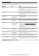
Thank you for choosing Lofrans. The Project 2000 is the new Lofrans windlass , designed for boat from 18 (59’) up to 25 mts (82’) length . Listed below are the technical features :
• Chromed Bronze finish as standard
• Nominal power with S2 parameter 60 minutes : 2000W 24V
• Peak power with S2 parameter 1 minute : 4000W 24V
• Available in AC motor : Three phases – Single phase (ask for details)
• Nickeled chain gipsy
• Cone clutches equipped
• Main shaft in stainless steel AISI 431
• Base bearing in stainless steel AISI 440
• Independent drum from gipsy
• Manual override equipped
• Haulage speed : from 18 up to 24 mt/min
• Ampere load : from 90 - 110 A
• Max pull measured with dynamometer : Kgs 1800 approx
• Weight : Kgs 73
SAFETY INFORMATION
• This product is not designed as a strong point to fasten your anchor rode. Fast the anchor rode to a strong point such as mooring cleat or similar.
• The vessel’s engine should always be running and used to assist in the recovery of the ground tackle.
• Always install the properly rated circuit breaker to protect the electric circuit and the motor from overheating and damage.
• Always turn off the main switch when the windlass is not in use to prevent accidental engagement.
• Always keep hands and feet clear of an operating windlass.If a jam occurs turn the windlass off at the main switch before clearing the anchor rode.
• Do not use the windlass for different purposes it was designed for.
WINDLASS WIRING MINIMUM REQUIREMENTS
Below there are the requirements for all the components of the windlass electric plant depending from the motor nominal power .
2000 W 24V
A-Battery capacity 150 Ah
B-Power cables size 50 mm² - 1 AWG
C-Lofrans Circuit breaker (slow time/current curve) 100 A
Fuse 5 A
Control wires size 1,5 mm² - 14 AWG
Notes
A. Battery of lower capacity decrease the windlass performances and are rapidly subjected to wear and tear.
B. This size must be increased when the length of the positive plus the negative cables are more than 25 mts. Use marine grade tinned copper wire.
C. The Lofrans circuit breaker protects the power line from short circuit and the windlass motor in case of overheating. It must be kept dry and installed in accessible place to be
promptly reactivated when it trips. It can be also used to isolate the windlass from the remote controls as we strongly suggest to avoid accidental engagement.
All the switches must be wired in parallel. We strongly recommend to have a minimum of two switches to operate the windlass in case one of them gets damage.
All Lofrans equipment is CE approved.
INSTALLATION GENERAL REQUIREMENTS
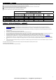
Proper installation of the windlass is critical and these essential conditions listed below need be fully satisfied :
Fig.1 The gipsy of the windlass must be in line with the bow roller.
Fig.2 The deck must be flat. The structure of the boat must be adequate to the load that the windlass is able to pull. If necessary reinforce the deck with a backing pad to spread the
stress.
Fig.3 When determining the position of the windlass , it is critical to locate it directly above the deepest area of the chain locker. As the chain falls into the chain locker , it must be
maximized because when the chain is stored. The chain tends to gather in the shape of a pyramid , which reduce the available space. If the chain pyramid falls , then overlaps
may occur, resulting in jams. The deeper the locker , the less likely this will occur. You must have a minimum of A=12” between the underside of the deck and the top of the
heaped chain. The chain locker shape is really important to limit the pyramid problem. The chain coming from the bow roller can be inclined up to 5 degrees.
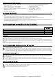
INSTALLATION PROCEDURE
Fig.4 Carefully position the template provided to the deck . Mark and drill the holes as indicated (see Fig.A). Sand smooth all edges and seal (see Fig.B). Clean the deck area.
Fig.5 Loosen the 4 hex nuts (391) to separate the topworks from the gearbox and motor. Seal the windlass base with high quality sealant. Position the topworks on the deck.
Fig.6 Join the gearbox to the windlass topworks by inserting the main shaft into the way of the gearbox. Align the motor away from the chain pipe.
Fig.7 Fasten a washer ,lock washer and hex nut to the remaining deck studs. Tighten all hardware properly. Connect the cables from the battery to the electric motor as shown in the
electric diagram.
TEST PROCEDURE
Fig.8 Introduce the chain into the gipsy . Please take care to keep hands and feet away of the incoming chain.
Fig.9 Turn on the remote control. Operate the UP switch. The chain will be recovered. Release the UP switch.Operate the DOWN switch. The chain will be released. If the windlass
runs in wrong direction change over the UP and DOWN wires at the control box.
Fig.10 After using the windlass , we strongly recommend that the nuts are checked again to ensure they are well tightened.
www.busse-yachtshop.de | info@busse-yachtshop.de