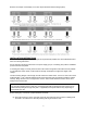
Installation and Operating Instructions (for chargers shown below) For additional information please call our Technical Support Group 800.742.
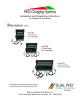
INSTALLATION AND OPERATING INSTRUCTIONS FOR THE FOLLOWING BATTERY CHARGING SYSTEMS: Model # Description Total Output Recreation Series PS1 PS2 PS3 One 6 Amp Bank Two 6 Amp Banks Three 6 Amp Banks 6 Amps 12 Amps 18 Amps Independently charge 12V batteries in the following systems: 12V 12V, 24V 12V, 24V or 36V IMPORTANT NOTICE Please save and read all safety, operating and installation instructions before installing or applying AC power to your PCS on-board battery charging system.
When using an extension cord, make sure: 1. That pins on the extension cord plug are the same number, size and shape as those of the charger’s plug; 2. That extension cord meets UL (Underwriters Laboratories, Inc.) acceptance and is in proper operating condition; 3. That wire size is large enough for the ac ampere rating of charger. Do not operate charger with a damaged cord or plug—replace the cord or plug immediately.
NEVER charge a frozen battery. PREPARING TO CHARGE If it is necessary to remove the battery or batteries to charge, always remove grounded terminal from battery first. Make sure all accessories are off, so as not to cause battery arcing. Be sure the area around any battery is well ventilated while batteries are being charged. On occasion, “gas fumes” may be present during charging and can be forcefully blown away by using a piece of cardboard or other nonmetallic material as a fan.
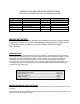
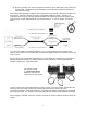
Below is an example of the display on a Three output Recreation Series Charger (RS3): INSTALLATION INSTRUCTIONS All PCS battery charging systems are designed to be permanently installed in a well-ventilated area and have no mounting restrictions. Do not make any electrical connections to the power supply (AC) or to a battery (DC) until the installation process has been completed. If mounting the charger in a boat, please choose a flat surface as high above the water level as possible.
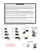
(b) All posts, terminals, and connectors should be cleaned to a shiny bright finish, using a wire brush or sand paper. This should be done periodically to assure maximum conductivity between the battery and the charger. Each charge cable assembly is equipped with a temperature sensor located at the junction of each set of ring terminals. Attempts to shorten the cables could partially disable the charger.
TROUBLE SHOOTING PROBLEM: No LED indicators illuminate on the charger. Solution Sequence: Check the AC power supply from its source through all connecting points up to the charger by using a meter or test light to confirm that current is being delivered to the charger. PROBLEM: The Green (POWER) LED is illuminated, but the Red (CHARGING) LED and the Green (READY) LED are off.
LIMITED WARRANTY Pro Charging Systems, LLC (PCS) makes this Limited Warranty only to the original retail purchaser. PCS warrants this battery charger for two years from the date of retail purchase against defective materials and/or workmanship. If such defects should occur, this unit will either be repaired or replaced at the discretion of the manufacturer.