
Instructions / Assembly

1.800.643.5596 • Lomanco, Inc. • lomanco.com
Subscribe on
YouTube
Find us on
Facebook
LomanCool
TM
2000
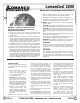
Power Vent Installation Instructions
INSTALLATION
1. Determine approximately where on
your roof you will place your Power
Ventilator.
• At the highest point in your
attic or air space. Best if
centered on roof length, and
less conspicuous if placed on
side away from street.
• IMPORTANT: Keep the highest
part of the dome lower than
the ridge line to ensure that
the dome's edge is NOT above
ridge line. (Typically, the center
of the vent should be about 24
inches down from the ridge.)
• Establish your position with
accuracy (because you will
want to duplicate it inside your
attic) by measuring down from
the ridge and over from the
roof edge.
2. Working now from the inside,
mark your planned opening (as
you established position when on
roof) and relocate your position to
be centered between two rafters.
Drive a nail into the roof so that
it can be easily found when you
return to the roof. Before you return
to the roof, be sure that you have:
(a) string or compass, (b) drill and drill
bit, (c) keyhole or electric jig (saber)
saw with a sharp coarse blade, (d)
ventilator and base, (e) roong nails
and hammer, and (f) roong cement
and applicator.
3. Using the nail driven from the inside
as center, scribe a 14” diameter circle
using string or compass. Care should
be taken not to make the hole too
large.
4. Drill a starting hole for sawing inside
the scribed circle.
5. Starting in the drilled hole, cut circular
opening, following the scribed line.
Use either keyhole or an electric jig
(saber) saw with a sharp coarse blade
to cut shingles and roof boards at
one time. If you do not have a coarse
blade, cut away shingles inside the
circle with utility knife before cutting
roof boards.
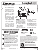
6. Carefully remove roong nails from
top row of shingles so that the
ashing of the ventilator will slide
under top row.
Slide ventilator carefully into place
with arrow pointing up, letting
thermostat hang down into opening.
Fasten the aluminum base to roof
boards with roong nails. Keep heads
of nails under shingles wherever
possible.
7. Finish the exterior mounting by
sealing all seams and nails with
roong cement. Use cement
also to fasten down loose edges
of shingles. Return to the attic.
You now have to mount the
thermostat and connect the wiring.
20500_1214
WARNING TO REDUCE THE RISK OF FIRE,
ELECTRIC SHOCK, OR INJURY TO PERSONS,
OBSERVE THE FOLLOWING:
A. Use this unit only in the manner intended by the
manufacturer. If you have any questions, contact the
manufacturer.
B. Before servicing or cleaning unit, switch power o at
service panel and lock service panel to prevent power
from being switched on accidentally. When the service
panel cannot be locked, securely fasten a prominent
warning device, such as a tag to the service panel.
C. Installation work and electrical wiring must be done
by qualied person(s) in accordance with all applicable
codes and standards, including re-rated construction.
D. Sucient air is needed for proper combustion and
exhausting of gases through the ue (chimney) of fuel-
burning equipment to prevent back drafting. Follow
the heating equipment manufacturer’s guide lines and
safety standards, such as those published by the National
Fire Protection Association (NFPA) and the American
Society for Heating, Refrigeration and Air Conditioning
Engineers (ASHRAE), and the local code authorities.
E. When cutting or drilling into wall or ceiling, do not
damage electrical wiring or other hidden utilities.
F. Ducted fans must always be vented to the outdoors.
G. If this unit is to be installed over a tub or shower, it must
be marked as appropriate for the application.
H. NEVER - place a switch where it can be reached from a
tub or a shower.
CAUTION For general ventilating use only. Do not use
to exhaust hazardous or explosive materials and vapors.
CAUTION This unit has an unguarded fan blade. Do not
use in locations readily accessible to people or animals.
This fan is intended for use facing an unoccupied space
only.
Be sure your fan is properly installed. Your fan is designed
to operate on 120 VAC 60 Hz.
Sharp edges are exposed during installation. Use gloves
and other safety equipment to avoid accidents.
WARNING To reduce the risk of re or electric shock,
do not use this fan with any solid state speed control.
IMPORTANT
With the power vent installed, at least 768 square inches
of inlet area must be provided. This is achieved by
installing 12, 8” x 16” intake vents, measuring 65 square
inches each.
OPERATION
Your ventilator will operate automatically as needed.
The adjustable thermostat has been set at the factory
to come on at 100°F., o at 85°F. The motor has been
permanently lubricated and does not require additional
lubrication.