
Instructions / Assembly

1.800.643.5596 • Lomanco, Inc. • lomanco.com
Subscribe on
YouTube
Find us on
Facebook
NOTE: If the dome is removed for
any reason, torque the mounting
screw to a maximum of 100 inch
pounds when reinstalled. CAUTION
- DO NOT OVERTIGHTEN
8. Position thermostat base high (in
the warmest part of the air space)
and above the ventilator opening.
Make sure that exible cable does
not touch the roof or rafters. (This
will eliminate vibration noise.)
The thermostat is a delicate
instrument, use screws instead of
nails when fastening bracket to roof
rafter.
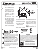
Your Lomanco Power Ventilator
MUST be wired as shown. Make all
connections inside the thermostat
box. Connect white (neutral) wire
from a power supply to white wire
on motor. Connect black (hot) wire
from power supply to black wire
on the thermostat and black wire
on switch. The other black wire on
the thermostat and black wire on
switch have been connected to
the black wire on the motor at the
factory but should be checked to
ensure a good tight connection.
The ground wire from the supply
should be connected to the ground
wire from the thermostat box.
9.
WARNING! Turn o power before
connecting power wires to ventilator.
Your power feed wire should be 14
gauge or larger wire size (two wires
plus ground). Take from thermostat
box and bring to power distribution
panel. Feed through bushing and
connect to 15-amp circuit breaker.
• Black to circuit breaker
• White to neutral base
• Plain to ground base
Recheck your connections then
turn the power on. You should
now enjoy the advantages of a
Power Ventilator, operating as the
thermostat demands.
A test switch has been provided.
To make sure your Lomanco Power
Ventilator is operating properly,
simply “PUSH TO TEST.” Caution
should be taken to ensure that no
body parts come in contact with any
of the vent’s moving parts during
this test.
NOTE: To control humidity in your
attic, a humidistat is also available.
LIMITED WARRANTY
Lomanco, Inc. Warrants this product for ve (5) years against any defects due to workmanship, parts or mechanical failure.
For warranty service the defective part must be sent, freight prepaid to Lomanco Inc. P.O. Box 519, 2101 West Main Street,
Jacksonville, Arkansas 72076. If the part is found to be defective it will be replaced with a new part at no charge and returned,
freight prepaid. This warranty does not include replacement due to destructive storms or labor cost incurred in the removal
of any defective part/product or installation of the new part/product. Online registration of the product at www.lomanco.
com within ten (10) days of the initial installation of the product is a condition precedent to warranty coverage. ANY IMPLIED
WARRANTIES OF MERCHANTABILITY AND FITNESS FOR A PARTICULAR PURPOSE ARE ALSO LIMITED IN DURATION TO FIVE
(5) YEARS. CONSEQUENTIAL DAMAGES TO PROPERTY RESULTING FROM A BREACH OF ANY WARRANTY MENTIONED HEREIN
ARE EXPRESSLY EXCLUDED. Some states do not allow limitations on how long an implied warranty lasts or do not allow
exclusion or limitation of consequential damages, so the above limitation may not apply to you. The warranty gives you
specic legal rights and you may also have other rights which
vary from state to state.
CSA
Approved
®
20500_1214
Parts and accessories available online at lomanco.com
Texas Department of
Insurance “Windstorm”
Approved
ONLINE WARRANTY REGISTRATION
Please ll out the online form at lomanco.com
to complete your warranty registration. If for
any reason you are unable to register your
product online please call 1.800.643.5596 and
we will assist you. Purchase and install date
information will be required.
LomanCool
TM
2000
Power Vent Installation Instructions
THREE
MUST
DO
Steps
to attic ventilation
Install all Exhaust Ventilation at the SAME HEIGHT with-
in a common attic area.
Installation of exhaust vents at more than one level on a roof allows
the upper exhaust vent to pull air in from lower exhaust vents rather
than from the intake vents. Intake air must come from intake vents
located near the lower part of the attic space to properly ventilate
the total attic area and eliminate weather infiltration.
Install ONLY ONE TYPE of Exhaust Ventilation within a
common attic area.
Exhaust Vents pull air from the easiest intake source. Vent types
cannot be mixed. The use of different types of exhaust vents could
make one of the vents act as intake for the other. Intake air must
come from intake vents located near the lower part of the attic
space to properly ventilate the total attic area and eliminate
weather infiltration.
Install a BALANCED SYSTEM of Intake and Exhaust
Ventilation.
50% Intake Ventilation - Intake vents located near the lower part
of the attic area are required to balance out your ventilation system.
50% Exhaust Ventilation - Use a Lomanco Ventilation Selector
Guide, or the calculators at lomanco.com to determine the number
of vents needed to properly ventilate an attic to meet the Ventilation
Minimum Property Standard.
1
2
3