
User's Manual


Installation and Setup
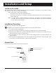
Hardware Provided
The system contains the transmitter keypad, an instruction booklet, an antenna, a strip of Velcro, rubber
feet, ethernet cable, and a 12-VDC power adapter.
Notice: Operation is subject to the following:
• This device may or may not cause interference.
• This device will accept any interference including interference that may cause undesired op-
eration of the unit.
Notice: To reduce potential radio interference to other users, the antenna type and gain should be
so chosen that the equivalent isotropically radiated power (EIRP) is not more than required
for successful communication.
Installation Procedure
The following is the basic installation procedure:
CAUTION: Do not mount the transmitter antenna near any large metal objects.
1. Un-wrap all system components.
2. Twist the 3” antenna onto the silver connector located on the rear of the transmitter.
3. Plug the power adapter into a standard 110/220V outlet and insert the barrel connector end into
the port located on the rear of the antenna.
4. Upon completion of setup, make sure pagers are fully charged and/or have good batteries and
are powered on.
5. The systems are shipped ready for the most general use. If you need to modify settings, refer
to the table of contents to locate a specific function guideline.
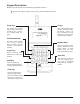
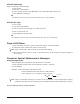
Connections
The following diagram shows the system connections.
Long Range Systems 4 LRS Connect Transmitter User Manual
110/220V ELECTRICAL SUPPLY
12 VDC POWER ADAPTER
ANTENNA
KEYPAD/TRANSMITTER
NETWORK/ETHERNET CABLE
(Optional)