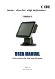
Fanless True Flat High Performance COBRA15 USER MANUAL 15”All-in-One True Flat Touch Screen POS System Version: 1.
COBRA15 About this Manual Thank you for purchasing LONGSHINE COBRA15 All-in-One system. This terminal offers all the enhanced features and is easy to connect to various optional devices for optimal performance. This user manual describes how you can setup and connect your terminal. Copyright The information in this guide is subject to change without prior notice.© Copyright 2012 All rights reserved.
COBRA15 Federal Communications Commission (FCC) Declaration of Conformity This device complies with part 15 of the FCC Rules. Operation is subject to the following two conditions: 1. This device may not cause harmful interference. 2. This device must accept any interference received, including interference that may cause undesirable operation. This equipment has been tested and found to comply within the limit of a Class A digital device, pursuant to Part 15 of the FCC Rules.
COBRA15 BEFORE YOU PROCEED Read the safety notices and the User Manual carefully before using the product. Keep the box and packaging in case the product needs to be shipped in the future. Follow the product and warning label instructions. For safety reasons, only qualified service personnel should open the terminal. Any changes or modifications that do not follow the instructions in this manual will void this product/s warranty.
COBRA15 ! OPERATING INSTRUCTIONS Keep the User Manual for future reference. Follow the product label instructions. Lay this terminal Upside down on a stable safe surface when installing. Heavy objects placed on the product can cause damage or obstruct proper ventilation. If one of the following situations arises, notify a qualified service technician immediately: a. The power cord or plug is damaged. b. The terminal has been dropped and damaged. c.
COBRA15 CONTENTS 1. Introduction ................................................................................................................................ 7 1.1 How to use this manual.............................................................................................. 7 1.2 A Visual tour of COBRA15........................................................................................... 8 1.2a What comes with COBRA15 ..........................................................................
COBRA15 1. Introduction Welcome Thanks you for choosing LONGSHINE COBRA15. COBRA15 was designed to help enhancing your business flexibility by offering a superior customer experience. 1.1 How to use this manual This manual contains all the information needed for setting up a COBRA15. In addition, you can also consult the manual for the instructions to assemble / to service the terminal and to install the optional peripherals. Introduction to COBRA15 and this user manual.
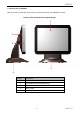
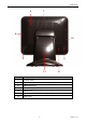
COBRA15 1.2 A Visual tour of COBRA15 Before you start, please take a few moments to become familiar with COBRA15 Terminal. Elegant, Solid, Fashionable and Compact Design 1 2 3 5 4 Item No Description 1 Touch screen 2 Removable Hard drive Extraction slot 3 POWER LED 4 Base / Stand 5 Optional devices 8 Version: 1.
COBRA15 7 6 8 10 9 9 11 Item No 12 Description 6 Function cover 7 Optional VFD ,7” and 10” Secondary Display cover 8 MSR & RFID cover 9 Speaker holes (speaker Optional) 10 Switch cover 11 VESA hole cover for 15”Secondary Display 12 Cable cover 9 Version: 1.
COBRA15 “Very Easy Maintenance” Please follow the instructions to reach all inner components: Step 1: Please position the terminal as shown below on a working table with “soft protective pad”. Step 2: Please remove cable cover by sliding it downwards. Push Push Step 4: Please disconnect and remove all the connected cables from IO interface and unscrew the HDD screw. Step 3: Please remove the circled six screws. 10 Version: 1.
COBRA15 Step 5: Please unplug and remove the hard disk. Step 6: The back cover can now be removed. Only authorized system engineers are advised to disassemble the device. Please be aware that unauthorized modifications will void your warranty. You are advised to contact your authorized supplier for technical support. 11 Version: 1.
COBRA15 1.2a What comes with COBRA15 Please check if your packaging contains below listed items before setting up your COBRA15. If any of the items is missing or damaged, please contact your supplier immediately. Main system with hidden power adapter in the stand. CD for product User Manual, Touch Kits and Peripherals Drivers & Utilities. M/B CD for user manual, drivers and utilities. M/B CD for Windows XP drivers and utilities.
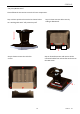
COBRA15 COBRA15 with second 15” LCD monitor COBRA15 with i-Button reader COBRA15 with ADDIMAT reader COBRA15 with 2D Image scanner COBRA15 with Fingerprint reader 13 Version: 1.
COBRA15 COBRA15 with VFD customer display 14 Version: 1.
COBRA15 1.2b Dimensions of COBRA15 and its optional peripherals 15” COBRA15 dimensions: 15” COBRA15 with MSR+RFID integrated: 15” COBRA15 with VFD customer display integrated: 15” COBRA15 with 15” second LCD monitor integrated: 15 Version: 1.
COBRA15 15” COBRA15 with ADDIMAT/i-Button/ Fingerprint/ 2D image scanner integrated: 15” COBRA15 with second 10” LCD monitor and 7” 4-Line customer display integrated: 16 Version: 1.
COBRA15 1.3 Features of COBRA15 Low power consumption LV (Low Voltage) design of the device is embedded with a unique chipset and CPU renders power saving function. Saving cost of ownership Modular design provides the owner with the following benefits: (a) cost effectiveness, (b) customization flexibility, and (c) Easy maintenance. Dust/water proof COBRA15 features a highly durable, rigorously tested design that is reliable and dependable in rugged environments.
COBRA15 1.4 IO Interface IO interface is located at the bottom of the display. To clearly see IO interface you must remove the cable cover. D H B A C E F G I Chart of the connector panel: Item No Description A Power DC-IN 12V B PS/2 Keyboard / Mice Output C 4 USB 2.
COBRA15 2. Hardware setup Getting Started This section describes how to install or to replace accessories and component on your COBRA15. 2.1 Pre-installation notice Before you start installing COBRA15 terminal, please read the following notices carefully. 1. COBRA15 terminal does not support PCI slot. 2. Do not plug in or unplug any interior devices, such as memory module or any function card, when the system power is still on. 3.
COBRA15 2.2 General information 2.2.1 COM port power voltage Warning!!Please check with your device provider for correct power voltage for each accessory. Incorrect power voltage setting can cause damage on device and terminal. Step 1: Please switch on COBRA15; BIOS message appears on the screen and the memory count begins. After the memory test, the message “Press DEL to run setup” will appear on the screen. Please press “DEL” on the keyboard to enter into BIOS. 20 Version: 1.
COBRA15 Step 2: Select “Serial Port Power Control Configuration” from the Tab “Advanced”. Step 3: Please check with your device provider for correct voltage on accessory and select correct power voltage for the accessory. Please NOTE that the default voltage is 0V. 21 Version: 1.
COBRA15 Step 4: Please press “ESC” on the keyboard to go back to main screen of BIOS and select ”Save Change and Reset” from the Tab”Save & Exit”. Please select “Yes” to exit BIOS. 22 Version: 1.
COBRA15 2.2.2 Cash drawer power voltage Step 1: Please switch on COBRA15; BIOS message appears on the screen and the memory count begins. After the memory test, the message “Press DEL to run setup” will appear on the screen. Step 2: Please select “Cash drawer VC Control” from the Tab “Advanced”. 23 Version: 1.
COBRA15 Step 3: Please check with your Cash Drawer provider for the correct voltage on Cash Drawer and select correct power voltage for Cash Drawer. Please NOTE that the default voltage for Cash drawer port is +24V. 24 Version: 1.
COBRA15 Step 4: Please press “ESC” on the keyboard to go back to main screen of BIOS and select “Save Change and Reset” from the Tab ”Save & Exit”. Please select “Yes” to exit BIOS. 25 Version: 1.
COBRA15 2.3 Hardware assembly Please make sure that the system power is turned off and the power supply is disconnected when making any hardware changes to COBRA15. 2.3.1 HDD + SSD Step 1: Please remove the HDD screw. Step 2: Please pull out and retrieve HDD or SSD. Step 3: Dismounting HDD from the tray requires two screws to be removed. Step 4: Then remove HDD or SSD from the tray. Step 5: Please insert new HDD or SSD into the tray.
COBRA15 Step 7: Please push in HDD or SSD into the terminal where indicated below. 27 Step 8: Please tighten the circled screw to complete the installation. Version: 1.
COBRA15 2.3.2 Memory Step 1: Please remove four screws indicated Step 2: Please see below where RAM module can be reached for replacement. below to expose memory module. NOTE: The memory is located in the upper portion of MB.(When replacing the memory module, please make sure that the memory is properly positioned and snapped into place)! DDR3-1 DDR3-0 28 Version: 1.
COBRA15 Please follow the instructions below to change memory on COBRA15. 1. Make sure that the terminal and all other peripherals which are connected to the terminal have been powered down and unplugged. 2. Disconnect all power cords and cables. 3. Locate the SO-DIMM socket on the system board. NOTE the key on the socket. The key ensures the module can be plugged into the socket in only one direction. 5.
COBRA15 7. Push down the module until the clips at each end of the socket lock into position. You will hear a distinctive click, indicating the module is correctly locked into position. Clip Clip 30 Version: 1.
COBRA15 2.3.3 Mini-PCI-E m-SATA SSD Step 1: Please position the terminal as shown below on a working table with “soft protective pad”. Step 2: Please remove cable cover by sliding it downwards. Push Push Step 4: Please disconnect and remove all the connected cables from IO interface and unscrew the HDD screw. Step 3: Please remove the circled six screws. 31 Version: 1.
COBRA15 Step 5: Please unplug and remove the hard disk. Step 6: The back cover can now be removed. Step 7: Mini PCI-E Connecter can then be found where circled. 32 Version: 1.
COBRA15 Step 8: Connect Pin Head and push header directly into Mini PCI-E Connecter. Step 9: Please reverse step 1~6 to assemble the terminal. Only authorized system engineers are advised to disassemble the device. Please be aware that unauthorized modifications will void your warranty. You are advised to contact your authorized supplier for technical support. 33 Version: 1.
COBRA15 2.3.3 CF card Step 1: Please position the terminal as shown below on a working table with “soft protective pad”. Step 2: Please remove cable cover by sliding it downwards. Push Push Step 4: Please disconnect and remove all the connected cables from IO interface and unscrew the HDD screw. Step 3: Please remove the circled six screws. 34 Version: 1.
COBRA15 Step 5: Please unplug and remove the hard disk. Step 6: The back cover can now be removed. Step 7: CF card slot can then be found where circled. 35 Version: 1.
COBRA15 Step 8: Please push CF card directly in place. Step 9: Please reverse step 1~6 to assemble the terminal. Only authorized system engineers are advised to disassemble the device. Please be aware that unauthorized modifications will void your warranty. You are advised to contact your authorized supplier for technical support. 36 Version: 1.
COBRA15 2.4 Optional peripherals installation 2.4.1 MSR + RFID Step 1: Please position the terminal as shown below on a working table with “soft protective pad”. Step 2: Please remove MSR cover to find USB connecter. Step 3: Please refer to the chart below for P/N assignment of USB. Terminal does not support P/S2 interface. MSR RFID Pin No function Pin No function 9 GND 10 5V 7 GND 8 Data - 4 Data + 6 Data + 3 Data - 4 GND 1 5V 2 GND 1 37 2 Version: 1.
COBRA15 Step 4: Please tightly plug in the connector into USB pin header in correct orientation. Step 5: Please sort the cable inside MSR housing and lock the two screws indicated below. Step 6: Integration completed. 38 Version: 1.
COBRA15 2.4.2 2-Line VFD customer display Step 1: Please remove four screws indicated below. Step 2: Please remove four screws indicated below to release the display cover. Step 3: Please check interface of VFD customer display. 39 Step 4: Please fix VFD to function cover as shown below. Cable should be led through the alignment hole. Version: 1.
COBRA15 Step 5: Please screw four screws indicated below to fix VFD customer display on to function cover. Step 6: Please refer to the follow drawing and adjust the jumper (JP7) on the motherboard to provide +5V/ +12V power for VFD customer display. NOTE: The device can choose either RS232 (as default) or USB (optional). Please contact your device provider for correct interface. 40 Version: 1.
COBRA15 Step 7: Please screw four screws indicated below to install VFD customer display to COBRA15. Step 8: Integration completed. Only authorized system engineers are advised to disassemble the device. Please be aware that unauthorized modifications will void your warranty. You are advised to contact your authorized supplier for technical support. 41 Version: 1.
COBRA15 2.4.3 i-Button reader Step 1: Please position the terminal as shown below on a working table with “soft protective pad”. Step 2: Please remove four screws indicated below. Step 3: Please remove the peripheral cover as shown below. Step 4: Please check the interface of i-Button before integration. NOTE: The device can choose either RJ-45 (RS232) as default or USB (optional). Please contact with your device provider for correct interface. 42 Version: 1.
COBRA15 Step 5: Please position the terminal as shown below on soft protective pad and screw four screws indicated in below diagram. Step 6: Please follow arrows in below diagram to sort the cable of i-Button. Step 7: Please remove cable cover by sliding it downwards. 43 Version: 1.
COBRA15 Step 8: If interface of i-Button is RJ45(RS232), please connect cable to COM1~COM4 which is RJ-45 type. If interface of i-Button is USB, please connect cable directly to USB port. Step 10: Integration completed. Step 9: Please assemble the cover back. Step 11: If interface of i-Button is COM port, please refer to 2.2.1 to change the power of COM port from 0 to +5V. 44 Version: 1.
COBRA15 2.4.4 ADDIMAT reader Step 1: Please position the terminal as shown below on a working table with “soft protective pad”. Step 2: Please remove four screws indicated below. Step 3: Please remove the peripheral cover as shown below. Step 4: Please see below diagram of ADDIMAT reader. Step 5: Please properly fit ADDIMAT reader to where circled. 45 Version: 1.
COBRA15 Step 6: Please position the terminal as shown below on soft protective pad and screw four screws indicated in below diagram. Step 7: Please follow arrows in below diagram to sort cable of ADDIMAT reader. Step 8: Please remove cable cover by sliding it downwards. 46 Version: 1.
COBRA15 Step 9: Please use RJ45 to D-SUB9 converter cable to connect with original cable from ADDIMAT reader and then connect converter cable to COM1~4. Step 10: Please fix the cable cover back to the terminal. Step 10: Integration completed. Step 11: If interface of ADDIMAT reader is COM, please refer to 2.2.1 to change the power of COM port from 0 to 5V. 47 Version: 1.
COBRA15 2.4.5 Second 7” 4-Line LCD display / 7” LCD display / 10” LCD display Step 1: Please remove screws indicated below. Step 2: Please remove four screws indicated below to release the display cover. Step 3: Please fix second display to function cover and screw four screws as shown below. Cable should be led through the alignment hole. 48 Version: 1.
COBRA15 Step 4: Please refer to the following drawings and connect the connectors (USB, VGA or RS232) of 7”, 10” second display to the correct connector on M/B. 49 Version: 1.
COBRA15 50 Version: 1.
COBRA15 Step 5: Please screw four screws indicated below to install LCD display to COBRA15. Step 6: Integration completed. 51 Version: 1.
COBRA15 2.4.6 15” second display Step 1: Please position the terminal as shown below on a working table with “soft protective pad”. Please remove cable cover by sliding it downwards. Step 2: Please push out VESA hole cover from inside the stand. 52 Version: 1.
COBRA15 Step 3: Please use four screws to fix VESA arm to the terminal as shown below. NOTE: VESA arm of 2nd 15” display was designed for standard 75cm VESA hole. Step 5: Please connect the cables to terminal 12V DC OUT and VGA. Step 4: Please sort and hide the cable through VESA arm and connect it to the terminal as instructed below. Step 6: Please close cable cover back in place. Step 7: Please change power adapter from 60W to 80W.
COBRA15 2.4.7 Fingerprint reader Step 1: Please position the terminal as shown below on a working table with”soft protective pad”. Step 2: Please remove four screws indicated below. Step 3: Please remove the peripheral cover as shown below. Step 4: Please properly fit Fingerprint reader to where circled. . 54 Version: 1.
COBRA15 Step 5: Please position the terminal as shown below on soft protective pad and screw four screws indicated in below diagram. NOTE: Cable should go through the hole. Step 6: Please follow arrows in below diagram to sort cable of Fingerprint reader. Step 7: Please remove cable cover by sliding it downwards. 55 Version: 1.
COBRA15 Step 8: For USB interface, please connect USB cable directly to USB port. Step 9: Please fix the cable cover back to the terminal. 56 Step 10: Integration completed. Version: 1.
COBRA15 2.4.8 2D image scanner Step 1: Please position the terminal as shown below on a working table with”soft protective pad”. Step 2: Please remove four screws indicated below. Step 3: Please remove the peripheral cover as shown below. Step 4: Please properly fit 2D image scanner to where circled. . 57 Version: 1.
COBRA15 Step 5: Please position the terminal as shown below on soft protective pad and screw four screws indicated in below diagram. NOTE: Cable should be go through the hole. Step 6: Please follow arrows in below diagram to sort cable of 2D image scanner. Step 7: Please remove cable cover by sliding it downwards. 58 Version: 1.
COBRA15 Step 8: For USB interface, please connect USB cable directly to USB port on the terminal. Step 9: Please fix the cable cover back to the terminal. 59 Step 10: Integration completed. Version: 1.
COBRA15 2.4.9 Internal speaker Step 1: Please position the terminal as shown below on a working table with “soft protective pad”. Step 2: Please remove cable cover by sliding it downwards. Push Push Step 4: Please disconnect and remove all the connected cables from IO interface and unscrew the HDD screw. Step 3: Please remove the circled six screws. 60 Version: 1.
COBRA15 Step 5: Please unplug and remove the hard disk. Step 6: The back cover can now be removed. Step 7: Internal left and right speaker can be integrated to COBRA15 with circled six screws in below diagram. 61 Version: 1.
COBRA15 Step 8: Please connect speaker cables directly to M/B Audio ports. Step 9: Reverse step 1-6 to assemble the terminal. 62 Version: 1.
COBRA15 2.4.10 WiFi Step 1: Please position the terminal as shown below on a working table with “soft protective pad”. Step 2: Please remove cable cover by sliding it downwards. Push Push Step 4: Please disconnect and remove all the connected cables from IO interface and unscrew the HDD screw. Step 3: Please remove the circled six screws. 63 Version: 1.
COBRA15 Step 5: Please unplug and remove the hard disk. Step 6: The back cover can now be removed. Step 7: Please align WiFi mini PCI-E card into mini PCI-E slot at an approximately 30 degrees on the slot and properly push it into the slot. 64 Version: 1.
COBRA15 Step 8: There are two antenna wires on WiFi module. Please fix internal antenna inside the front bezel shown below on the left hand side. Please nicely sort external antenna cable where shown below on the right top corner to connected to external antenna. ANT1: External antenna ANT2: Internal antenna Internal antenna External antenna connecter 65 Version: 1.
COBRA15 External antenna Step 9: Please reverse step 1-6 to assemble the machine. 66 Version: 1.
COBRA15 3. Service manual 3.1 Touch panel Step 1: Please position the terminal as shown below on a working table with “soft protective pad”. Step 2: Please remove cable cover by sliding it downwards. Push Push Step 4: Please disconnect and remove all the connected cables from IO interface and unscrew the HDD screw. Step 3: Please remove the circled six screws. 67 Version: 1.
COBRA15 Step 5: Please unplug and remove the hard disk. Step 6: The back cover can now be removed. Step 7: Please remove eight screws indicated below to separate touch panel from COBRA15. Step 8: After touch panel is replaced, please reverse the step 1-7 to assemble the machine. 68 Version: 1.
COBRA15 3.2 LCD panel Step 1: Please position the terminal as shown below on a working table with “soft protective pad”. Step 2: Please remove cable cover by sliding it downwards. Push Push Step 4: Please disconnect and remove all the connected cables from IO interface and unscrew the HDD screw. Step 3: Please remove the circled six screws. 69 Version: 1.
COBRA15 Step 5: Please unplug and remove the hard disk. Step 6: The back cover can now be removed. Step 7: Remove 4 screws for holder and 4 screws for touch panel. Then you can separate touch pane from COBRA15. 70 Version: 1.
COBRA15 Step 8: Please loosen four screws and disconnect the inverter and touch connectors to remove LCD. Step 9: Please disconnect LVDS cable to separate LCD from M/B. Step 10: Please reverse step 1-9 to assemble the machine. 71 Version: 1.
COBRA15 3.3 Motherboard Step 1: Please position the terminal as shown below on a working table with “soft protective pad”. Step 2: Please remove cable cover by sliding it downwards. Push Push Step 4: Please disconnect and remove all the connected cables from IO interface and unscrew the HDD screw. Step 3: Please remove the circled six screws. 72 Version: 1.
COBRA15 Step 5: Please unplug and remove the hard disk. Step 6: The back cover can now be removed. Step 7: Please disconnect all indicated connectors on M/B 73 Version: 1.
COBRA15 Step 8: Please remove four screws from M/B to separate and replace motherboard from COBRA15. Step 9: Please reverse step 1-8 to assemble the machine. 74 Version: 1.
COBRA15 4. Specification Technical Information COBRA15 System Specifications Technical Requirements CPU Core Logic BIOS VGA Controller Intel N2800 1.86 GHz, 1M Cache, BGA (6.55W) Intel NM10 Family Express Chipset AMI VGA Controller Intel GMA 3650 graphics will run at 640 MHz -Two 204-pin DDR3 SDRAM Small Outline Dual Inline Memory Module (SO-DIMM) sockets. Memory -C11Support for DDR3 800 MHz and DDR3 1066 MHz SO-DIMM.
COBRA15 PRINTER DC in 1 1 2 PIN DC JACK.