Table of Contents 1. 2. 3. 4. 5. Introduction...................................................................................................................................3 1.1 Welcome......................................................................................................................3 1.2 Product Feature .........................................................................................................3 1.3 Contents of Package.................................................
1. Introduction 1.1 Welcome PCI Adapter connects you with IEEE802.11n networks at receiving rate up to an incredible 300Mbps! By using the reflection signal, 802.11n technology increases the range and reduces "dead spots in the wireless coverage area. Unlike ordinary wireless networking of 802.11b/g standards that are confused by wireless reflections, 802.11n can actually use these reflections to increase four times transmission range of 802.11g products.
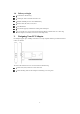
1.4 Before you begin You must have the following: A desktop PC with an available 32-bit PCI slot Minimum 300MHz processor and 32MB memory Windows 2000, XP, 2003, Vista, Win 7 A CD-ROM Drive PCI controller properly installed and working in the desktop PC 802.11n or 802.11b/g Access Point (for infrastructure Mode) or another 802.11n or 802.11b/g wireless adapter (for Ad-Hoc; Peer-to-Peer networking mode.) 2. Designing Your PCI Adapter PCI Adapter supports up to 300Mbps connections.
3. Installation 3.1 Install Your PCI Adapter Open your PC case and locate an available PCI on the motherboard. Slide PCI Adapter into the PCI slot. Make sure that all of its pins are touching the slot's contacts. You may have to apply a bit of pressure to slide PCI Adapter all the way in. after it is firmly in place, secure its fastening tab to your PC's chassis with a mounting screw. Then close your PC. Attach the external antennas to PCI Adapter's antenna port. Power on the PC.
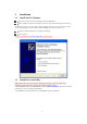
3. Click Next.
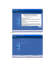
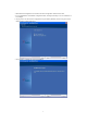
4. Select Ralink Configuration Tool or Microsoft Zero Configuration Tool then click Next. a. Its recommended to select Ralink Configuration Tool, which provides fully access to all function of PCI Adapter. b. If you prefer to use the wireless configuration tool provided by Windows XP or Vista, please select Microsoft Zero Configuration Tool. 5. Click Finish to complete the software installation.
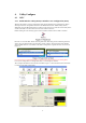
4. Utility Configure 4.1 WZC 4.1.1 Ralink Wireless Utility (RaUI) or Windows Zero Configuration (WZC) Windows XP includes a wireless configuration utility named "Windows Zero configuration" (WZC) which provides basic configuration functions to the Ralink Wireless NIC. Ralink's utility (RaUI) additionally provides WPA functionality. To make it easier for the user to select the correct utility. RaUI will let users make a selection when it first runs after windows XP boots.
When activating WZC, there are several differences with the RaUI status, compared to the RaUI status without WZC running. The profile button will be gray. Profile functionality is removed since the NIC is controlled by WZC. The Connect and Add to Profile function will be gray. Profile functionality is removed since the NIC is controlled by WZC. Please read through this document for full details on the other functions provided by RaUI. 4.1.
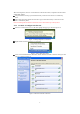
Select the intended access point and click "Connect". Then click "Connect Anyway" as shown as Figure 1-7.
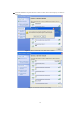
If you want to modify information about the AP, click "Change advanced settings "as shown in Figure 1-9. Then select the "Wireless Networks" tab shown as Figure 1-10.
Click "Properties" as shown in Figure 1-11. Then click "OK" button. Figure 1-11 AP's properties After filling in the appropriate value, click "OK." The pop-up will indicate the status as shown in Figure 1-12.
Clicking the Ralink icon will bring up the RaUI main window. Users can find the surrounding APs in the list. The currently connected AP will be shown with a blue icon beside it, as shown in Figure 1-13. Users may use the advanced tab to configure more advanced features provided by Ralink's wireless NIC. For details on configuring the advanced features, please check the Advance setting section. Figure 1-13 Show connection status by using WZC to initiate the connection 4.2 RaUI 4.2.1 Start 4.2.1.
Figure 2-1-1 RaUI section introduction There are three sections to the RaUI dialog box. These sections are briefly described as follow. Button Section: Include buttons for selecting the Profile page, Network page, Advanced page, Statistics page, WMM page, WPS page, SSO page, CCX page, and about button, Radio On/Off button and Help.
Function Section: Appears to present information and options related to the button.
Figure 2-1-9 WMM page Figure 2-1-10 WPS page Figure 2-1-11 SSO page Figure 2-1-12 CCX page 16
Figure 2-1-13 About page Status Section: This section includes information about the link status, authentication status, AP's information and configuration, and retrying the connection when authentication is failed.
Figure 2-1-16 APs Information Figure 2-1-17 Configuration When starting RaUI, a small Ralink icon appears in the notifications area of the taskbar, as shown in Figure 2-1-15. You can double click it to maximize the dialog box if you selected to close it earlier. You may also use the mouse's right button to close RaUI utility. Figure 2-1-18 Ralink icon in system tray Additionally, the small icon will change color to reflect current wireless network connection status. The status is shown as follows: 4.2.
Figure 2-2-1 Profile function Definition of each field: Profile Name: Name of profile, preset to PROF* (* indicate 1, 2, 3...). SSID: The access point or Ad-hoc name. Network Type: Indicates the networks type, including infrastructure and Ad-Hoc. Authentication: Indicates the authentication mode used. Encryption: Indicates the encryption Type used. Use 802.1x: Shows if the 802.1x feature is used or not. Cannel: Channel in use for Ad-Hoc mode.
4.2.2.2 Add/Edit Profile There are three methods to open the Profile Editor dialog box. You can open it by clicking the "Add to Profile" button in the Site Survey tab. You can open it by clicking the "Add" button in the Profile tab. You can open it by clicking the "Edit" button on the Profile tab. Figure 2-2-2 Configuration Profile Name: The user can chose any name for this profile, or use the default name defined by system.
length. WEP Key: Only valid when using WEP encryption algorithms. The key must be identical to the AP's key. There are several formats to enter the keys. 1. Hexadecimal - 40bits: 10 Hex characters. 2. Hexadecimal - 128bits: 26Hex characters. 3. ASCII - 40bits: 5 ASCII characters. 4. ASCII - 128bits: 13 ASCII characters. 4.2.2.3 Example to Add Profile in Profile Click "Add" below the Profile List. The "Add Profile" will appear.
Specify a Profile Name. Select an AP from the SSID drop-down list. The AP list from the last Network. Now the profile which the user set appears in the profile list. Click "Activate".
4.2.3 Network 4.2.3.1 Network The system will display the information of local APs from the last scan result as part of the Network section. The Listed information includes the SSID, BSSID, Signal, Channel, Encryption algorithm, Authentication and Network type as shown in Figure 2-3-1-1. Figure 2-3-1-1 Network function Definition of each field: SSID: Name of BSS or IBSS network. Network Type: Network type in use, Infrastructure for BSS, Ad-Hoc for IBSS network. Channel: Channel in use.
Connected network: When RaUI first runs, it will select the best AP to connect to automatically. If the user wants to use another AP, they can click "Connect" for the intended AP to make a connection. If the intended network uses encryption other than "Not Use," RaUI will bring up the security page and let the user input the appropriate information to make the connection. Please refer to the example on how to fill in the security information.
4.2.3.
The System section will appear at the bottom of the Add Profile window. You can specify your own profile name. Next, you will see the new profile in the profile list.
4.2.4 Advanced Figure 2-4 Advance function Wireless mode: Select wireless mode. 2.4G, 5G and 2.4+5G are supported. Wireless Protection: Users can choose from Auto, on, and off. (This is not supported by 802.11n adapters.) Auto: STA will dynamically change as AP announcement. On: The frames are always sent with protection. Off: The frames are always sent without protection. TX Rate: Manually select the transfer rate. The default setting is auto. (802.
Figure 2-5-1 Statistics function Transmit Statistics: Frames Transmitted Successfully: Frames successfully sent. Frames Fail To Receive ACK After All Retries: Frames failed transmit after hitting retry limit. RTS Frames Successfully Receive CTS: Successfully receive CTS after sending RTS frame. RTS Frames Fail To Receive CTS: Failed to receive CTS after sending RTS. Frames Retransmitted Successfully: Successfully retransmitted frames numbers. Reset counters to zero.
4.2.6 WMM 4.2.6.1 WMM Figure 2-6-1 shows WMM function of RaUI. It involves "WMM Enable", "WMM -Power Save Enable" and DLS setup. The introduction indicates as follow: Figure 2-6-1 WMM function WMM Enable: Enable Wi-Fi Multi-Media. The setting method follows Section 2-6-2. WMM - Power save Enable: Enable WMM Power Save. The setting method follows Section 2-6-3. Direct Link Setup Enable: Enable DLS (Direct Link Setup). The setting method follows Section 2-6-4. 4.2.6.
The DLS settings are explained as follows: Fill in the blanks of Direct Link with MAC Address of STA. The STA must conform to these two conditions: 1. Connect with an AP that supports DLS features. 2. Ensure that DLS is enabled. The Timeout Value indicates the time in seconds before it disconnects automatically. The value is an integer. The integer must be between 0~65535. A zero value specifies that it stays connected. The default Timeout Value is 60seconds. Click "Apply" 4.2.6.
Change to "Network" function. And add a AP that supports WMM features to a Profile. The result will look like the below figure in Profile page. 4.2.6.4 Example to Configure to Enable WMM-Power Save Click "WMM-Power save Enable". Please select which ACs you want to enable. The setting of enabling WMM-Power Save is successfully.
4.2.7 WPS 4.2.7.1 WPS Figure 2-7-1 WPS function WPS Configuration: The primary goal of Wi-Fi Protected Setup (Wi-Fi Simple Configuration) is to simplify the security setup and management of Wi-Fi networks. Ralink STA supports the configuration and setup using a PIN configuration method or a PBC configuration method through an internal or external Registrar. WPS AP List: Displays the information of the surrounding APs with WPS IE from the last scan result.
Config Mode: The station serving as an Enrollee or an external Registrar. Table of Credentials: Displays all credentials obtained by the Registrar. The detailed list includes information about the SSID, MAC Address, Authentication and Encryption Type. If STA is the Enrollee, the credentials are created immediately with each WPS success. If STA is the Registrar, RaUI creates a new credential withWPA2-PSK/AES/64Hex-Key and doesn't change this until switching to STA Registrar. Control items for credentials. 1.
4.2.7.2 WPS Information on AP The WPS information (shown below) includes the authentication type, encryption type, Config methods, device password ID, selected registrar, state, version, AP setup locked, UUID-E and RF bands. Authentication Type: There are three authentication modes supported by RaConfig. They are open, Shared, WPA-PSK and WPA system. Encryption Type: For open and shared authentication mode, the selection of encryption type are None and WEP.
Device Password ID: Indicates the method or identifies the specific password that the selected Registrar intends to use. The AP in PBC mode must indicate0x0004 within the two-minute Walk Time. Value Description 0x0000 Default(PIN) 0x0001 User-specified 0x0002 Rekey 0x0003 Display 0x0004 Push Button (PBC) 0x0005 Registrar-specified 0x0006-0x000F Reserved Selected Registrar: Indicates if the user has recently activated a Registrar to add an Enrollee. The values are "TRUE" and "FALSE".
Click "Rescan" to update available WPS APs. Select an AP (SSID/BSSID) that STA will join to. Click "PIN" to enter the PIN Enter the PIN Code of the STA into the Registrar when prompted by the Registrar. The user can also click "Rotate" to rotate to the next credential usable credential.
Describe "WPS Status Bar" - "PIN - xxx" as follow: Acceptable PIN Configurations: Start PIN connection - SSID ~> Begin associating to WPS AP ~> Associated to WPS AP ~> Sending EAPOL-Start ~> Sending EAP-Rsp (ID) ~> Receive EAP-Req(Start) ~> Sending M1 ~> Received M2 ~> (Received M2D ~> Sending EAP-Rsp(ACK)) ~> Sending M3 ~> Received M4 ~> Sending M5 ~> Received M6 ~>Sending M7 ~> Received M8 ~> Sending EAP-Rsp(Done) ~> Configured ~> WPS status is disconnected ~> WPS status is connected successfully-SSID WPS
2. Click PBC to start the PBC connection. 3. Push the PBC on AP. *Allow time for an exchange between Step 2 and Step 3. 4. The progress bar as shown in the figure below indicates that scanning progress. 5. When one AP is found, join it.
6. Check WPS Information on the available WPS APs 7. Configure and receive one or more credential(s). 8. Then connect successfully. The result will be displayed as it is in the figure below.
Describe "WPS Status Bar" -"PBC - xxx" as follow : A successful PBC Configuration : Start PBC connection ~> Scanning AP ~> Begin associating to WPS AP ~> Associated to WPS AP ~> Sending EAPOL-Start ~> Sending EAP-Rsp (ID) ~> Receive EAP-Rsp (Start) ~> Sending M1 ~> Received M2 ~> Sending M3 ~> Received M4 ~> Sending M5 ~> Received M6 ~> Sending M7 ~> Received M8 ~> Sending EAP-Rsp (Done) ~> Configured ~> WPS status is disconnected ~> WPS status is connected successfully-SSID No PBC AP available : Scanning A
AP2 is a G-Band AP using PBC mode. (ID = 0x0004) They have the different UUID-E. STA would regard these two APs as two different APs and wait until only one PBC AP is available. 4.2.7.5 Example to Configure a Network/AP Using PIN or PBC Method Select Registrar from the Config Mode drop-down list. Enter the details of the credential and change configurations (SSID, Authentication, Encryption and Key) manually if needed. If the PIN configuration is setup, enter the PIN sent from the Enrollee.
Start PIN or PBC. The following procedures are as similar as section 2-7-3 (PIN Enrollee Setup) or section 2-7-4(PBC Enrollee Setup) If your AP Enrollee has been configured before the WPS process, the credential you set in advance will be updated to the AP itself. Otherwise, after a successful registration, the AP Enrollee will be re-configured with the new parameters, and the STA Registrar will connect to the AP Enrollee with these new parameters.
Connect to Ralink's website: Ralink Technology, Corp. Display Configuration Utility, Driver, and EEPROM version information. Display Wireless NIC MAC address. 4.2.9 Link Status The link status page displays detailed information about the current connection as shown in Figure 2-9. Figure 2-9 Link Status function Status: Current connection status. If no connection, if will show Disconnected. Otherwise, the SSID and BSSID will show here. Extra Info: Display link status in use.
4.3 Security 4.3.1 Auth.\Encry. Setting-WEP/TKIP/AES Figure 3-1 Auth.\Encry. Settings Authentication Type: There are 7 authentication modes supported by RaUI. They are open, Shared, LEAP, WPA and WPA-PSK, WPA2 and WPA2-PSK. Encryption Type: For open and shared authentication mode, the available encryption types are None and WEP. For WPA, WPA2, WPA-PSK and WPA2-PSKauthentication mode, the encryption type supports both TKIP and AES. 8021X: This is introduced in the topic of Section 3-2.
authentication and can be used to dynamically generate user-based and session-based WEP keys to secure subsequent communications between the WLAN client and the access point. TTLS: Tunneled Transport Layer Security. This security method provides for certificate-based, mutual authentication of the client and network through an encrypted channel. Unlike EAP-TLS, EAP-TTLS requires only server-side certificates. EAP-FAST: Flexible Authentication via Secure Tunneling. It was developed by Cisco.
Certificate issuer: Select the server that issues the certificate. Allow intermediate certificates: It must be in the server certificate chain between the server certificate and the server specified in the "certificate issuer must be" field. Server name: Enter an authentication sever root. 4.3.3 Example to Reconnect 802.1x Authenticated Connection after 802.1x Authenticated connection is failed in Profile There are two situations where a user is able to reconnect an 802.
When a "Timeout" occurs; Choose "PEAP" as the Authentication type and key-in "wpatest2" as the identity .Tunnel Protocol is "EAP-MSCHAP-v2 and the tunnel identity is "wpatest2". The tunnel password is "test2". These settings are the same as our intended AP's setting. When a "Timeout" occurs, The following dialog box will be displayed; If it has connected successfully, the dialog box will appear as follows; 4.3.
The Auth.\Encry. function will appear as below; Enter 1234567890 in the Key#1 Hexadecimal field. This value is same as our intended AP's setting. Click "OK".
4.3.5 Example to Configure connection with WPA-PSK Select the AP with a WPA-PSK authentication mode and click Connect. Select WPA-PSK as the Authentication Type. Select TKIP or AES encryption. Enter the WPA Pre-Shared Key. Click OK. Be careful, if the WPA Pre-Shared Key entered is not correct, you wont be able to exchange any data frames, even though the AP can be connected.
4.3.6 Example to configure connection with WPA Select an AP with WPA authentication mode and click Connect. Select WPA as the Authentication Type. Click 802.1x and the setting page will appear. 1. PEAP: Select EAP-MSCHAP v2 from the drop-down list for tunnel authentication and key-in the tunnel identity as wpatest2 and the tunnel password as test2 . These settings are the same as our intended APs setting. Then click OK.
2. TLS/Smart Card: SelectTLS/Smart Card from the Authentication type drop-down list. TLS only requires the identification to be set as wpatest2 for server authentication. TLS must use client certification. Click Client Certification and select a certification for server authentication. Then click OK.
3. TTLS: Select TTLS from the Authentication type drop-down list. Key-in the identity as wpatest2 and password. These settings are the same as our intended APs setting. Then click OK. 4. EAP-FAST: Select EAP-FAST from the Authentication type drop-down list. Key-in the identity as wpatest2 password and a domain name into the blank field. These settings are the same as our intended APs setting. Then click OK.
5. Trouble Shooting This chapter provides solutions to problems that may occur during the installation and operation of PCI Adapter. Read the descriptions below to solve your problems. 1. The PCI Adapter does not work properly. Reinsert PCI Adapter into your PCs PCI slot. Right click on My Computer and select Properties. Select the device manager and click on the Network Adapter. You will find PCI Adapter if it is installed successfully.
FCC ID: VYTLP-7665 FCC Compliance and Advisory Statement This device complies with Part 15 of the FCC rules. Operation is subject to the following two conditions:(1) this device may not cause harmful interference, and (2) this device must accept any interference received, including interference that may cause undesired operation. This equipment has been tested and found to comply with the limits for a Class B digital device, according to Part 15 of the FCC rules.