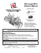
DVL Insert EF II Owner's Manual Featuring the Burner Tested and Listed by OMNI-Test Laboratories, Inc. Beaverton, Oregon Report # 028-F-72-5 ANSI Z21.88 • Direct Vent Fireplace Insert • Masonry or Factory Built (Metal) Wood-Burning Fireplace • Residential or Mobile Home WARNING: If the information in these instructions is not followed exactly, a fire or explosion may result causing property damage, personal injury or loss of life.
Introduction Introduction We welcome you as a new owner of a DVL Insert. In purchasing this fireplace insert you have joined the growing ranks of concerned individuals whose selection of an energy system reflects both a concern for the environment and aesthetics. It is one of the finest home heaters the world over. This manual will explain the installation, operation, and maintenance of this heater.
Table of Contents Introduction and Important Information Finalizing the Installation Introduction ......................................................2 Glass Frame Removal and Installation .................20 Log Set Installation............................................22 Steps for Finalizing the Installation.......................24 Pilot Flame Inspection .......................................24 Air Shutter Adjustment .......................................
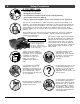
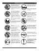
Safety Precautions IF YOU SMELL GAS: * * * * * Do not light any appliance Extinguish any open flame Do not touch any electrical switch or plug or unplug anything Open windows and vacate building Call gas supplier from neighbor's house, if not reached, call fire department This unit must be installed by a qualified installer to prevent the possibility of an explosion. Your dealer will know the requirements in your area and can inform you of those people considered qualified.
Safety Precautions AA AA AA AA A Do not place clothing or other flammable items on or near the heater. Because this heater can be controlled by a thermostat there is a possibility of the heater turning on and igniting any items placed on or near it. The viewing glass should be opened only for lighting the pilot or conducting service. Do not operate with cracked, broken, or removed glass. Operate the heater according to the instructions included in this manual.
Features and Specifications Features • • • • • • • • Installation Options Works During Power Outages (millivolt system) High Efficiency Optional Thermostat or Remote Control Ember Fyre™ Burner for "Wood Fire" Look Quiet Blower for Effective Heat Distribution Convenient Operating Controls Variable-Rate Heat Output Low Maintenance • • • Residential or Mobile Home Fireplace Insert Masonry or Factory Built (Metal) WoodBurning Fireplace Heating Specifications Approximate Heating Capacity (in square feet
Installation (for qualified installers only) Installation Warnings • Failure to follow all of the requirements may result in property damage, bodily injury, or even death. • This heater must be installed by a qualified installer who has gone through a training program for the installation of direct vent gas appliances. • This appliance must be installed in accordance with all local codes, if any; if not, follow ANSI Z223.1 and NFPA 54(88).
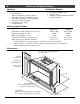
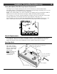
Installation (for qualified installers only) Top Convection Deflector Install the top convection deflector as shown to the right. The deflector is shipped on top of the insert. The screws are shipped inside the owner's pack. Fireplace Requirements • Insert must be placed within a code-conforming masonry fireplace or tested and listed factorybuilt (metal) wood-burning fireplace. Repair any fireplace damage prior to installation.
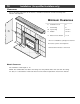
Installation (for qualified installers only) Factory-Built (Metal) Wood-Burning Fireplace Requirements The damper ("A ") and grate (with log set) ("B ") must be removed (see the illustration below) The smoke shelf ("C "), internal baffles ("D "), screen ("E "), masonry lining or refractory ("G " & "I"), and metal or glass doors ("F ") may be removed (if applicable) NOTE: If any internal baffle is cut, bent, or removed, the fireplace must be permanently marked to indicate that it has been altered and is n
Installation (for qualified installers only) Clearances Due to the high temperature of the heater, it should be located out of traffic and away from furniture and draperies.
Installation (for qualified installers only) Face Sizing Face Height Width Rawhide Victorian Rosario Cambridge Craftsman Bungalow Classic Arched, Artisan Metropolitan Architectural Series Discovery Wilmington 27” 27” 26” 25-7/8” 27-1/2” 27” 26-1/2” 26-1/2” 27-7/8” 26’ 27” 35-3/4” 35-3/4” 35-3/4” 37-5/8” 36” 32-3/4” 34-3/4” 34-3/4” 33-5/8” 35-3/4’ 36-1/8” Notes Side begins arch 3-1/2” below top - 45” radius Face Mounting Brackets – Arched, Artisan, Metropolitan, Victorian Lace Some Arched, Artisa
Installation (for qualified installers only) Gas Line Requirements MASSACHUSETTS INSTALLATIONS - WARNING: THIS PRODUCT MUST BE INSTALLED BY A LICENSED PLUMBER OR GAS FITTER WHEN INSTALLED WITHIN THE COMMONWEALTH OF MASSACHUSETTS. OTHER MASSACHUSETTS CODE REQUIREMENTS: • Flexible connector must not be longer than 36 inches. • Shutoff valve must be a “T” handle gas cock. • Only direct vent sealed combustion products are approved for bedrooms or bathrooms.
Installation (for qualified installers only) Vent Requirements • The gas appliance and vent system must be vented directly to the outside of the building, and never be attached to a chimney serving a separate solid fuel or gas-burning appliance. Each direct vent gas appliance must use it's own separate vent system. • Make sure the exhaust pipe on the heater connects to the exhaust portion of the cap. The illustrations below show how the flex liners should be attached.
Installation (for qualified installers only) Vent Restrictor WARNING: Restrictor adjustment should only be done by a qualified installer. Only those installations determined to be over-drafting require this adjustment. The best indication of over-drafting is a hyper-active flame pattern (flames that move too quickly). If the air shutter is constricted, the flames become short and yellow, yet still very active. Over-drafting may affect the pilot, but this is not the best way to determine over-drafting.
Installation (for qualified installers only) Vent Location • A vent restrictor is built into the appliance to adjust the flow rate of exhaust gases. This ensures proper combustion for all vent configurations. Depending upon the vent configuration, you may be required to adjust the restrictor position. The charts for acceptable vent configurations detail the correct vent restrictor position. Center Line Inlet (3” Dia.) Exhaust (4” Dia.
Installation (for qualified installers only) Vent Connector Removal and Installation • The vent connector is shipped attached to the insert, but may be removed to facilitate tight installations. See the directions below for installation. 1. Route the flex vent through the chimney from above (leave an extra 3' at the top). Make sure the flex is thoroughly stretched. 2. Remove the vent connector and attach it to the flex vent (see the instructions on the following page).
Installation (for qualified installers only) 17 Vent Connector Removal and Installation (continued) Vent Connector Removal Pull the vent connector rod forward. Slide the vent connector to the WARNING: The anti-seize on the vent connector can stain rear. It will "snap" out. clothing, carpets, or other items. Vent Connector Installation A A A Attach the flex vent to the vent connector. A AAAA Slide the insert into place, lining up these guides with the edges of the vent connector.
Installation (for qualified installers only) Installation Without Surround Panels The insert may be installed without surround panels. Mount the on/off switch and rheostat to the control panel under the burner pan (see “Installation of the On/Off Switch and Rheostat” on page 19). Surround Panel Installation 1 PANEL SIZE 8" x 10" Rectangular Arched (8” x 10”) 10” x 13” Rectangular Follow the directions below WIDTH 44-3/16" 44-3/16" 48-3/16" to install the HEIGHT 33-3/8" 33-3/8" 36-3/8" side panels.
Installation (for qualified installers only) Installation of the On/Off Switch and Rheostat The on/off switch and rheostat may be installed in either the surround panels or control panel. See the illustration below for installation details. WARNING: Make sure the heater Upper Right of Trim (preferred) Control Panel (next to gas control valve) is unpluged before installing the rheostat. AA AA AA AA AAA AA A A AAA AA AA AA AA AA Disconnect the red and brown wires leading to the on/off switch.
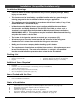
Finalizing the Installation Glass Frame Removal and Installation Warning: The appliance must be completely cool before removing the glass. Warning: Do not strike or slam the glass. Note: a If using a Victorian Lace or Bungalow face, attach the arch covers after installing the glass. Spring Pin Open the four latches holding the glass frame in place (start with the two below the glass) - follow the directions shown to the right. Top of Firebox Insert the 1/4” key into the spring pin.
Finalizing the Installation Glass Frame Removal and Installation (continued) The spring pin can come loose from the latch assembly. This occurs when it is turned 1/4 turn when it is disengaged. Follow the directions below to re-install the spring pin if it becomes loose. To re-install the spring pin, first insert this end into a 1/4” key. NOTE: The spring pins can be installed with the glass frame in place or removed. Insert the spring pin into this bracket with the pins aligned vertically.
Finalizing the Installation Log Set Installation Step 1 - Install the logs A AA AAA Place the rear log on the two platforms at the rear of the firebox. AA AA AAA AAA AA AAA AAA AA AA AA These pins insert into the holes in the log. AA AA Place the front logs on top of the burner. AA AA AA AA AA AA AA AA AA These bolts insert into the holes in the logs. Top View Do not place logs over burner holes. Note how the front left log is spaced 1/4” to 3/8” off of the 1” to 1-1/2” space burner holes.
Finalizing the Installation Step 2 - Install the twigs, ember chunk, kibbles, and rock wool Place the left and right twigs as shown. AA AA AA AA AA AA AAAA AA AA AA AA A AAAA AA AAA AA AA AA Place the ember chunk as shown. AA AA AA AAA A AA AA AA Place the kibbles in a random pattern. Make sure to place them over any exposed screws or metal to create a desirable effect. Do not place kibbles directly over the burner holes.
Finalizing the Installation Steps for Finalizing the Installation 1. Remove the glass (see page 20). NOTE: If using propane (LP) convert the appliance prior to installing the logs. 2. We recommend you purge the gas line at this time (with the glass removed). This allows gas to be detected once it enters the firebox, ensuring gas does not build up. 3. Turn on gas to the heater. Leak test all gas joints prior to starting the appliance. Start the pilot. Start the main burner.
Finalizing the Installation FINE TUNING THE EMBER-FYRE™ BURNER Each installation is affected by altitude, vent configuration, and fuel quality. Because of this, the restrictor and air shutter may need to be fine tuned to each installation. Follow the hints below to finetune the burner for optimum performance and aesthetics. Restrictor Adjustment: Only those installations determined to be over-drafting require this adjustment. See the instructions on page 14 for details.
Operation Before You Begin • Read this entire manual before you use your new heater (especially the section "Safety Precautions" on pages 4 & 5). Failure to follow the instructions may result in property damage, bodily injury, or even death. Location of Controls OFF The Pilot Flame can be LO found below the back log.
Operation 27 Starting The Pilot Flame The pilot flame is required to ignite the main burners (it also plays a safety role). It should be left on once lit. It will stay lit unless the gas control valve is turned to "OFF". However, the pilot will go out if the gas is shut off, the propane tank runs out (or low) or if the stove malfunctions. If the pilot turns off frequently, call your dealer for information.
Operation Starting the Heater for the First Time • Burn the heater at a high setting with the blower off for an extended period (up to 48 hours). This will cure the painted surfaces. Fumes from the paint curing and oil burning off the steel will occur. This is normal. We recommend opening a window to vent the room. • Condensation may appear on the glass each time you start the heater - this is normal. • Blue Flames will occur on the heater when it first comes on.
Operation 29 Adjusting the Blower Speed The blower helps transfer heat from the heater into the room. It will not turn on until the heater is up to temperature (approximately 10 minutes after starting). See the illustration below for instructions on adjusting the blower speed. OFF Turn the dial all the way counter-clockwise until it clicks off. LOW HIGH The high position is all the way counter-clockwise, without clicking off. Turn the dial all the way clockwise.
Maintenance Maintaining Your Heater's Appearance Fingerprints or other marks left on the optional plated surface may become etched in place if they are not wiped clean prior to turning the heater on. Clean the plated surfaces with denatured alcohol and a soft cloth (with the heater cool). Other cleaners may leave a film that may become etched into the surface. Yearly Service Procedure • Failure to inspect and maintain the heater may lead to improper combustion and a potentially dangerous situation.
Maintenance Troubleshooting Table Problem: Pilot Will Not Light Main Burners Will Not Start Remote Control Does Not Work Thermostat Does Not Work Heater Will Not Possible Cause: Don't Call for Service Until You: A gas shut off valve is turned off Check all gas shut off valves The gas control knob isn't turned to "PILOT" See "Starting the Pilot Light" Step C The valve control knob isn't pushed in See "Starting the Pilot Light" Step C The igniter wasn't pressed repeatedly See "Starting the P
Maintenance How this Heater Works This heater was designed with safety as the primary concern. Many of the components inside this heater are for safety purposes. Therefore, only certified gas service technicians should service this heater. What Turns the Main Burners On and Off CL O CK By e Sco at ed tt e Cr The main burners are switched on and off using the electricity generated by the thermopile. The ON/OFF switch, remote control, or thermostat control the circuit to the main burner.
Maintenance Wiring Diagram Thermocouple Thermopile Piezo Igniter Red AA AA Brown On/Off Switch Copper Co-Axial Wire Orange Red Spark Electrode White Pilot Hood Rheostat Hot (black) Common (white) Black Power In Molex Connector Ground (green) Caution: Black Black Blowers Snap Disk White Black White White Green Ground (attached to stove) Label all wires prior to disconnection when servicing controls. Wiring errors can cause improper and dangerous operation.
Safety Label Safety Label The safety (listing) label is attached to the operating tag (chained to the heater near the gas control valve).
Limited 7 Year Warranty 35 To register your TRAVIS INDUSTRIES, INC. 7 Year Warranty, complete the enclosed Warranty card and mail it within ten (10) days of the appliance purchase date to: TRAVIS INDUSTRIES, INC., 4800 Harbour Pointe Blvd. SW, Mukilteo, WA 98275. TRAVIS INDUSTRIES, INC. warrants this gas appliance (appliance is defined as the equipment manufactured by Travis Industries, Inc.
Optional Equipment (for qualified installers only) LP Conversion Instructions Install the conversion kit prior to installing the gas line to ensure proper gas use. 1 Remove the glass (see page 20). Remove the logs and coals (if installed - page 22) 2 Remove the burner (see illustration below). WARNING: Do not disassemble the burner – screws on the burner must be left in place. b a Remove the firebox floor. Lift the pilot hood off the pilot assembly (you may need to pull hard to remove).
Optional Equipment (for qualified installers only) 3 Follow the directions below to replace the orifices. a Slide the air shutters all the way to the left. Rear Orifice AA AA AA AA b Use a 1/2” open end wrench to unscrew both orifices. Front Orifice Manifold c 1/2" Wrench Rear Burner Apply thread sealant to the LP Orifice orifices prior to installation. Use d Screw the LP orifice in so the the chart below to identify the Front Burner orifice shoulder protrudes 5/16” correct orifices.
Optional Equipment 5 Install the logs and embers. 6 Replace glass and face. 7 Remove the regulator from the front of the gas control valve. Replace with the propane regulator, using the new gasket and screws included with the regulator. NOTE: Leak test this area after the heater is installed, gas is connected, and the main burner is lit. (for qualified installers only) a Remove and discard the three screws using a slotted screwdriver of Torx T-20.
Optional Equipment (for qualified installers only) 39 Firebacks WARNING Turn off gas to the appliance and make sure it has fully cooled prior to conducting service. 1 Remove the glass frame and logs (see the manual for details). IMPORTANT INSTALLATION NOTE FOR MODELS USING THE ACCENT LIGHT: Follow the steps below if installing the firebacks with an accent light. • • • • • 2 Remove the burner (see page 36). Install the rear fireback (see the directions below). Install the accent light (page 41).
3 Optional Equipment (for qualified installers only) Install the side firebacks following the directions to the right. Remove this clip 4 Restore the fireplace to the correct configuration. attached to the firebox ceiling (both sides).
Optional Equipment (for qualified installers only) Accent Light Make sure power to the heater has been turned off prior to installation (unplug the power cord). Do not connect 110-120 VAC to the gas control valve or the on/off circuit on this fireplace. IMPORTANT INSTALLATION NOTE FOR MODELS USING THE FIREBACKS: 1 Follow the steps below if installing the firebacks with an accent light. • Remove the burner. • Install the rear fireback. • Install the accent light. • Replace the burner.
4 Optional Equipment (for qualified installers only) Attach the rheostat assembly and wiring harness as shown below. AA AA AA c Attach the quickconnect from the accent light to the quick-connect on the rheostat wiring harness. NOTE: Make sure the grounding wire remains attached (if applicable). d Use the included wire nut to connect the wire leading from the rheostat to the remaining wire leading from the accent light. a Disconnect the molex connector leading to the power cord.
Optional Equipment (for qualified installers only) Lower Surround Panel The older lower surround panel (sku 98500619 and 98500628) are installed in a different fashion than illustrated in the instruction sheet included with the panel. Follow the directions below. 1 Prepare the panel following the directions below. Use the larger DVL Insert Bracket Secure the lower panel to the bracket with the nuts (included with the panel).
Index Additional Items Required ....................................7 Adjusting the Blower Speed ..................................29 Adjusting the Flame Height ..................................28 Air Shutter Adjustment ........................................24 Altitude Considerations........................................13 Before You Begin ...............................................26 Blower Operation.................................................29 Cap (Termination) Requirements............