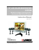
5" LCD COLOR OBSERVATION SYSTEM With Built-In 4 Channel Triplex Digital Video Recorder and 4 Night Vision CCD Cameras Instruction Manual English Version 1.0 MODEL: L15LD400 Series www.lorexcctv.com Copyright © 2007 LOREX Technology Inc.
Thank you for purchasing the L15LD400 Series Observation System. Lorex is committed to providing our customers with a high quality, reliable security product. The L15LD400 Series observation system is one of the most sophisticated video security systems on the market today with many of the same advanced features you will find in “high security” systems used in banks and casinos.
Important Safeguards Important Safeguards In addition to the careful attention devoted to quality standards in the manufacture process of your video product, safety is a major factor in the design of every instrument. However, safety is your responsibility too. This sheet lists important information that will help to assure your enjoyment and proper use of the video product and accessory equipment. Please read them carefully before operating and using your video product. Installation 1.
Important Safeguards Service Use 13. Servicing - Do not attempt to service this video equipment yourself as opening or removing covers may expose you to dangerous voltage or other hazards. Refer all servicing to qualified service personnel. 19. Cleaning - Unplug the video product from the wall outlet before cleaning. Do not use liquid cleaners or aerosol cleaners. Use a damp cloth for cleaning. 14.
General Precautions NOTE This equipment has been certified and found to comply with the limits regulated by FCC, EMC, and LVD. Therefore, it is designated to provide reasonable protection against interference and will not cause interference with other appliance usage.
L15LD400 Series Feature List L15LD400 Series Feature List Monitor • 15" High Resolution LCD Monitor with built in DVR • Mouse control interface (mouse included) • Trilingual interface (English, Spanish and French) • Supports DDNS (Dynamic Domain Name Server) • Commercial grade monitor stand • Wall or Rack mountable (mounts sold separately) • A full range of LOREX Pro Series CCTV cameras available for use with this system Built-In Digital Video Recorder (DVR) • Triplex Technology allows for recording, play
Table of Contents Table of Contents Getting Started .......................................................................................... 9 L15LD400 Series - Front .................................................................. 10 - 12 L15LD400 Series - Side .......................................................................... 13 L15LD400 Series - Back ......................................................................... 14 Remote Control ...................................................
Table of Contents Configuration .................................................................................... 37 - 40 HDD MANAGEMENT ................................................................................................................ 37 CAMERA SETUP ...................................................................................................................... 38 MOTION SETUP ...........................................................................................................
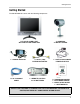
Getting Started Getting Started The SG19LD804-161 comes with the following components: LCD & DVR COMBO UNIT WITH INSTALLED 160 GB HDD 1 x POWER ADAPToR 1 x 10’ ETHERNET CABLE 4 x 60 FT. (18M) EXTENSION CABLES 1 x REMOTE CONTROL 2 x AA BATTERIES 4 x CAMERAS 4 x METAL STANDS 1 x 4-SPLITTER CAMERA POWER ADAPTOR 1 x HARDWARE MANUAL 1 x SOFTWARE MANUAL 1 x QUICK START GUIDE 1 x SOFTWARE CD CHECK YOUR PACKAGE TO CONFIRM THAT YOU HAVE RECEIVED THE COMPLETE SYSTEM, INCLUDING ALL COMPONENTS SHOWN ABOVE.
L15LD400 Series - Front L15LD400 Series - Front 1 7 8 2 9 3 4 5 10 6 11 1. DISPLAY CONTROL BUTTONS - Control the onscreen display of Cameras: • SEQ - Displays cameras 1~4 in Full Screen Sequencing Mode • PIP - Displays cameras in Picture in Picture mode. The displayed cameras can be set by selecting either the main screen or PIP screen, and selecting a number 1~4. • ZOOM - Zooms in on the currently displayed camera (1x Zoom).
L15LD400 Series - Front L15LD400 Series - Front 1 7 8 2 9 3 4 10 5 6 11 7. IR RECEIVER & LED INDICATORS: • IR RECEIVER - Receiver for the Remote Controller signal. • DVR STATUS LEDs: z POWER - Power LED indicator for the System power status (ON/OFF). z HDD - HDD access LED indicated when activity is taking place on the system Hard drive. 8. 0~9 BUTTONS - Switches the full screen view between channels 1~4. Numbers 0~9 are used to enter the System Password. 9.
L15LD400 Series - Front L15LD400 Series - Front 1 7 8 2 3 9 4 10 5 6 11 10. PLAYBACK CONTROLS: • BACK – Reverses the playback. • STOP - Stops the playback. • PAUSE – Pauses the playback. • PLAY - Plays back the recorded data. • REW - Fast Rewind of the playback • STEP - Playback step by step (frame by frame) • FF - Fast Forward of the playback 11. DIRECTION ARROWS & ENTER: • DIRECTION ARROWS - Moves the mouse cursor and navigates within the System Menu.
L15LD400 Series - Side L15LD400 Series - Side 1 2 3 4 5 1. REMOVABLE DRIVE BAY - Drive bay to install a removable Hard Drive. 2. DRIVE BAY LOCK - Locking mechanism for the removable drive. 3. USB BACKUP PORT - Connect a USB memory stick or USB HDD for data backup 4. DEVICE PORT - Connect to a PC for firmware upgrade. 5. USB MOUSE PORT - Connection port for a USB Mouse (alternate control for the System).
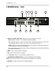
L15LD400 Series - Back L15LD400 Series - Back 1 2 3 4 5 6 7 8 1. ALARM BLOCK CHART - Outlines the Alarm Block connections 2. RS-232C - Connection port to the PC or for other DVR control devices 3. ALARM BLOCK & RS485 CONNECTIONS - Controls Alarm devices, and for direct connection to PTZ cameras. 4 sensor inputs and 1 relay output. 4. ETHERNET - Connects the System to a network router or other Ethernet Device. 5. CH 1~4 - BNC Camera inputs for Channels 1~4. 6.
Remote Control Remote Control Listed below is a quick reference for the Remote Control. MENU BUTTON Opens the Main Menu (system setup) PIP Changes the display to Picture in Picture mode SEQUENCE Turns camera Sequence Mode ON/ OFF. P/T Controls the PTZ Camera (not included). VOLUME + / - ZOOM Zooms in on the current image ENTER BUTTON Applies a configuration change in Menu Mode. NAVIGATION CONTROLS Navigates in MENU and SEARCH mode. Adjusts the zoomed area in ZOOM mode.
MC7521 Cameras MC7521 Cameras The System includes 4 CCD Color IR Day/Night Indoor/Outdoor Cameras* INFRA-RED LEDs Provides illumination for low light conditions CAMERA LENS STAND Stand connects to the Camera for mounting to walls, ceilings and other surfaces INPUT CABLE - BNC Sends Video to the System INPUT CABLE - POWER Provides power for the camera. * Picture changes from Color to B&W under low light conditions.
Camera Installation Camera Installation Before you install the camera, carefully plan where and how you will position the camera, and where you will route the cable that connects the camera to the System. Installation Warnings: • Select a location for the camera that provides a clear view of the area you want to monitor, which is free from dust, and is not in line-of-sight to a strong light source or direct sunlight.
Camera Installation Connecting Cameras 1. Connect the Female BNC end of the supplied 60’ extension’ cable to the camera. Connect the male Power end of the extension cable to the camera. IMPORTANT NOTE: The ends of the extension cable are NOT the same - one end has a Male power port, and the other has a Female power port.
Camera Installation 2. Connect the Female end of the supplied 60’ extension cable to an open BNC camera input on the back of the System. Connect the female Power end of the extension cable to the 4-cable power adaptor. NOTE: To access the Connection Ports for the System, the monitor can be tilted forward (for easier access).
Connecting the Mouse Connecting the Mouse Connect the supplied mouse to the PS/2 Port on the back of the unit. Alternatively, a mouse can be connected to the USB port located on the side of the unit. USB Connection - A mouse can be connected to the PS/2 Port on the back of the unit. USB Connection - A mouse can be connected to the USB Port on the side of the unit. The port will be labelled to indicate the connection type. Mouse Controls LEFT MOUSE Click to activate a function.
Display Modes Display Modes Initial Loading Sequence • Connect the POWER cable located on the back of the Observation System. The unit will automatically power on. • The System will load the firmware • The System will perform a Hard Drive check. • The unit will initially load to a split screen view, displaying all 4 cameras (if available). NOTE: If a new HARD DRIVE is detected, the system will prompt you to FORMAT the drive.
Display Modes Network Status Indicators The Network Indicators appear when a remote connection is made to the unit: • Indicates that there is no client connection. • Indicates that a client is connected to the system. Recording Mode Indicators The Recording Mode Indicators appear in YELLOW when a camera is recording: • Indicates that the camera is recording in ALARM Mode. • Indicates that the camera is recording in MOTION DETECTION Mode. • Indicates that the camera is recording in CONTINUOUS Mode.
Display Modes Display Modes Cameras can be displayed in Single, Quad, Sequence or PIP modes by pressing the buttons on the front panel of the System, or by using the mouse to click on the onscreen icons.
Display Modes Sequence Display Mode Displays cameras in sequence. Press the SEQ Button on the front panel of the System, or use the mouse to select the onscreen sequence icon. Press the SEQ Button on the front panel. Select Sequence mode by using the mouse to select the sequence icon. NOTE: The sequence can be adjusted using the MENU SETUP. PIP Display Mode Displays cameras in PIP (Picture in Picture) Mode.
Display Modes Zoom Mode Displays a single camera in ZOOM Mode (200% Zoom). Select the channel to ZOOM, and press the ZOOM button on the front panel of the System, or use the mouse to select the onscreen ZOOM icon. The area of ZOOM can be moved using the front panel arrows, or by using the Mouse. Press the ZOOM Button on the front panel. Select ZOOM mode by using the mouse to select the ZOOM icon. PTZ (Pan/Tilt/Zoom) & Focus Controls Enters PTZ control for a PTZ type camera installed on Channel 1.
Recording Mode Recording Mode RECORDING MODE: • Indicates that the camera is recording in ALARM Mode. • Indicates that the camera is recording in MOTION DETECTION Mode. • Indicates that the camera is recording in CONTINUOUS Mode. HDD STATUS The HDD Status bar indicates the total hard drive amount, and the amount of drive space currently in use.
Recording Mode Recording Mode RECORDING STATUS • Red Icon: Indicates the system is recording in Schedule, Motion or Alarm Mode. • White Icon: Indicates that the record schedule is not set to record. If the unit loses power, recording will automatically resume once power is restored (based on the recording schedule setup). For more information on Regarding Mode Setup, please refer to the RECORD SETUP on page 26-27.
Playback Playback Starting Playback Mode Press the PLAY button on the front panel of the System, or click the onscreen PLAY icon to start playback, starting from the most recent recording.
Playback Stopping Playback Mode Press the STOP button on the front panel of the System, or click the onscreen STOP icon to stop the playback. Search Mode Press the SEARCH button on the front panel of the System, or click the onscreen SEARCH icon to search through previously recorded data. There are 3 modes for search: PERCENT SEARCH - Search by appointing a recording percentage. TIME/DATE SEARCH - Search by appointing a time and date EVENT SEARCH - Search by Event list.
Playback Percent Search • Use the Mouse wheel to select the recording percentage on the search bar. • Click “PLAY” to confirm and start the playback. Time/Date Search • START - Set the start time and date for the recording. • END - Set the end time and date for the recording. • TARGET - Enter the target time and date to start playback. Select the time and date using the Mouse wheel to adjust the numbers. Click PLAY to start playback, or ESC to cancel.
Playback Event Search • TIME/DATE - Displays the event time and date. • CHANNEL - Displays the channel in which the event occurred. • EVENT - Displays the event type: z z z MOT - Motion detection LOS - Image lost ALM- Alarm trigger The system keeps up to 1000 events in its EVENT LIST. Use the Left Mouse button to select the events, and use the Mouse wheel to switch pages.
Playback The playback speed can also be adjusted using the Front Panel buttons or Remote Control: While in playback mode, use the direction keys on the remote control to adjust the speed: z z z z X times high-speed playback. X times low speed playback. Rewind. Play To increase the speed: REW key (High-speed backward playback) FF key (High-speed forward Playback). z Press the keys repeatedly to adjust the speed rate. z z To decrease the speed Use the STEP keys to Slow playback (in reverse or forward).
System Setup and Navigation System Setup and Navigation Press the MENU button on the Front panel or Remote, or click the onscreen MENU icon to log into system: • Click the 0~9 icons (or use the front panel buttons) to enter the password. • Click ENTER to confirm and enter the system. • Default ADMIN password: leave blank (No default password. Press ENTER key directly to enter the system) • Navigate using the arrows. Use ENTER to accept an option, and ESC to exit the menu.
System Setup and Navigation Display Setup - Screen Setup 1. VERTICAL POSITION - Adjust the vertical position of the image. 2. HORIZONTAL POSITION - Adjust the horizontal position of the image. 3. BORDER ENABLE - Enable the display of border. 4. BORDER WIDTH - Adjusts the width of border. 5. BORDER COLOR - Adjusts the color of the border. Display Setup - OSD Setup 1. TOP OSD OFFSET - Adjusts the position of Top OSD. 2. BOTTOM OSD OFFSET - Adjust the position of bottom OSD.
Record Setup Record Setup 1. RECORD SETUP - Set up recording mode, resolution, picture quality, and recording frame rate. 2. SCHEDULE SETUP - Program the recording schedule. Record Setup - Record Configuration 1. CHANNEL - Select a Channel to configure. 2. RESOLUTION - Set the recording resolution: • 704×240 (NTSC) / 720×288(PAL) • 352×240 (NTSC) / 360×288(PAL) 3. QUALITY - Set the recording picture quality to High / Normal / Low.
Record Setup Record Setup - Schedule Setup 1. CHANNEL - Select a single channel to setup the schedule. 2. TYPE - Select a recording mode: • Continuous Recording: constantly occurring. Recording is • Motion: Begins the recording when motion is detected. • Alarm: Begins the recording when an alarm is detected • Motion and Alarm: Sets the system to record when Motion and/or an Alarm is detected. 3. 0~24 Hour - Activate or deactivate the schedule for a particular hour in a week. 4.
Configuration Configuration 1. HDD MANAGEMENT - Includes HDD SETUP (HDD Clear), and HDD INFORMATION. 2. CAMERA SETUP - Includes CAMERA TITLE and CAMERA COLOR SETUP. 3. MOTION SETUP - Includes SENSITIVITY, DURATION, DETECT CELL NUMBER. 4. ALARM SETUP - Set up the Alarm mode (N.C. or N.O) and the Alarm Output Duration. 5. INTERVAL SETUP - Set up the switch interval of the Full screen and the PIP screen. 6. TIME/DATE SETUP - Program the system date and time. 7. PASSWORD SETUP - Setup the password. 8.
Configuration CAMERA SETUP 1. CHANNEL - Select the camera to be modified. 2. TITLE - Input the camera Title, max. 8 characters. 3. BRIGHTNESS - Adjust image brightness (-32~31). 4. CONTRAST - Adjust color contrast (-32~31). 5. SATURATION - Adjust color saturation (-32~31). 6. HUE - Adjust color hue (-32~31). MOTION SETUP 1. CHANNEL - Select a channel for the setup. 2. SENSITIVITY GRADE - Adjusts the motion detection sensitivity. 1 (LOW)~5 (VERY HIGH) 3.
Configuration ALARM SETUP 1. CHANNEL - Select a channel for the setup. 2. ALARM INPUT - Set up the Alarm Input type. • NORMALLY CLOSED - The Alarm is triggered when the circuit is closed (ON). • NORMALLY OPEN - The Alarm is triggered when the circuit is opened (OFF). 3. DURATION - Setup for the post-alarm recording duration, and the alarm output duration. The duration setting is applied to both functions. The setting range is from 1 second to 99 seconds.
Configuration TIME/DATE SETUP The date and time set by the manufacturer may be different from your time zone. It is very important to configure the system date and time before starting recording. Set the date and time by using Mouse wheel: • DATE FORMAT- Asia/American/European • TIME FORMAT- 12 hours/24 hours • MONTH FORMAT- English/Numeric NOTE: It is strongly recommended to Set the time/ date, Reset all factory defaults and CLEAR the Hard Drive. PASSWORD SETUP The password consists of 1 to 8 digits.
EXTERNAL DEVICE EXTERNAL DEVICE 1. TCP/IP SETUP - Configure the system Networking information. 2. PAN/TILT SETUP - Set up the parameters of the PTZ control. 3. SPOT SETUP - SPOT output setup. 4. RS232C SETUP - Set up the parameters of the RS232 port. TCP/IP SETUP - IP SETUP 1. MAC ADDRESS - Displays the MAC address. MAC address cannot be changed and is unique to each system. 2. DHCP MODE - Set the DHCP mode to Manual or Automatic.
EXTERNAL DEVICE 3. INTERVAL - Set the interval for the system to report its IP address to the DDNS server automatically. (D- day / H- hour / M- minute). Use the Mouse Wheel to change the value. 4. REGISTER - Connect to the DDNS server and register the system information to the server. Click REGISTER to start the registration. 5.
EXTERNAL DEVICE PAN/TILT SETUP - SPEED SETUP 1. PAN SPEED - Set the PANing speed (0 low ~ 7 high). 2. TILT SPEED - Set the TILTing speed (0 low ~ 7 high). 3. ZOOM SPEED - Set the speed of ZOOM IN/OUT (0 low ~ 7 high). SPOT SETUP 1. SWITCH INTERVAL - Sets the sequence switching time (01 ~ 99 sec.). 2. ALARM POP UP - When an Alarm is detected, the corresponding channel (connected to the Alarm sensor block) pops up onscreen. 3. MOTION POP UP - Sets the MOTION detection pop-up to ON/OFF. 4.
BACKUP RS232C SETUP Users can connect the System to a PC through the RS232 port. Other system control devices can also be connected through the RS232 port. The ASCII-Code information is in Serial port setup (Users cannot change value in this setting). 1. BAUDRATE - The transmission baudrate is 19200bps. 2. LENGTH - The transmission length is 8 bits. 3. STOP BIT - The stop bit is 1. 4. PARITY - The parity is none. BACKUP USB BACKUP SUBMENU 1.
Data Backup Data Backup System status messages: • USB STATUS - Insert USB Key - the system will check the available space. When choosing a backup size, leave 20MB as a buffer and do not use the full space of the USB Stick. FIRMWARE UPGRADE The system firmware can be updated using a USB Memory stick: 1. Select the FIRMWARE UPGRADE menu and insert the Memory Stick containing the firmware. 2. Click the CD-CHECK. 3. Once the CD-CHECK UPGRADE. is complete, click 4.
Troubleshooting Troubleshooting When a malfunction occurs, it may not be serious and can be corrected easily. The following describes the most common problems and solutions. Please refer to the following before calling Lorex Technical Support: Problem: Observation System Unit is not receiving power, or is not powering up Check: • Confirm that all cables are connected correctly. • Confirm that the power adaptor is securely connected to the back of the unit.
Observation System Specifications - Appendix #1 Observation System Specifications - Appendix #1 Monitor Specifications LCD Panel Diagonal: 15.0” TFT, Input: TTL / LVDS. LCD Display Resolution 1280 x 1024 Video Input 4CH (4 x BNC) Video Output Monitor / Spot (BNC x 1) Split Screen Full screen, Quad split Zoom Available PIP (Picture in Picture) Available LCD Color Resolution 16.7 M (8 bits) LCD Pixel Pitch 0.297mm (H) x 0.
MC7521 Camera Specifications - Appendix #2 MC7521 Camera Specifications - Appendix #2 Image Device 1/4" Interline transfer type color CCD Effective Pixels NTSC: 512 H x 492 V (252k PIXELS) PAL: 512 H x 582 V (298k PIXELS) Scanning System NTSC: 525 Lines 2:1 Interlace PAL: 625 Lines 2:1 Interlace Resolution Horizontal 420 TV lines Shutter Speed NTSC: 1/60 ~ 1/10,000 sec. PAL: 1/50 ~ 1/10,000 sec. S/N Ratio More than 48dB (AGC off) Sync. System Internal Min. Illumination 1.
Full Connectivity Diagram - Appendix #3 Full Connectivity Diagram - Appendix #3 The following diagram outlines a general set of connections available with the Observation System.
Connecting a Slave (Spot-Out) Monitor - Appendix #4 Connecting a Slave (Spot-Out) Monitor - Appendix #4 Connections to a Slave Monitor / Spot-Out Monitor (not included with the System) can be made through the VIDEO OUT and/or the SPOT OUT ports on the back of the Observation System. A slave monitor can be a TV or Computer Monitor with VGA inputs. A Slave Monitor is used as a View Only device.
Connecting Motion / Alarm Device - Appendix #5 Connecting Motion / Alarm Device - Appendix #5 Motion detection and Alarm controls are enabled through the Menu system on the Observation System. Additional motion sensor devices can be connected to the system (Motion Sensors, Door/Window Sensors).
Connecting PTZ Cameras - Appendix #6 Connecting PTZ Cameras - Appendix #6 PTZ Cameras (not included with this system) can be connected to the PTZ Control Block on the back panel of the System. The PTZ Controls are enabled through the Menu system on the Observation System. Additional PTZ Cameras are available at http://www.lorexcctv.com Installing a PTZ (RS-45 Type) PTZ Camera: 1. Connect the Transmit Cable to the D+ port on the PTZ Control Block on the Observation System. 2.
Connecting to a PC using the Serial Port - Appendix #7 Connecting to a PC using the Serial Port - Appendix #7 The Observation System can be connected directly to a PC COM Port by using the Serial Port located on the back of the system. • To connect DVR to a PC, users must use a twisted RS232 cable (See below). • The RS232 settings (baudrate/ parity/ length/ stop bit) are NOT adjustable. The transmission baudrate is 19200bps, length 8 bits, stop bit 1, and the parity is none. ASCII-CODE is 1 BYTE.
Hard Drive Replacement - Appendix #8 Hard Drive Replacement - Appendix #8 The Hard Drive serves the same purpose in an Observation System as a video cassette does in a VCR. Please follow the steps carefully in order to ensure proper installation. The compartment located on the front panel of the DVR is the removable Cartridge Casing in which you insert the Hard Drive. The various parts of the Cartridge Casing are labeled for your reference. STEP 1: Remove the Cartridge Casing from the DVR.
Hard Drive Replacement - Appendix #8 STEP 4: Secure the Hard Drive in the Casing • Use screws and tighten them, positioning the Hard Drive into place. This step is optional, but it is recommended. Position Hard Drive and secure with provided screws STEP 5: Slide the top Cover over the Cartridge Casing • Slide the Cover forward over the Cartridge Case. Ensure it is secured in place over the release latch.
Optional Accessories Optional Accessories The following accessories are available to add to your existing system: SLAVE / SPOT OUT MONITOR BNC TYPE CAMERAS EXTENSION CABLE Slave / Spot Out Monitors View selected Cameras on a second Monitor Additional BNC Type Cameras Extends the length between the CAMERA and MONITOR. Available in 60’ length. PTZ CAMERAS Accessory PTZ Cameras for additional view control.
Version 1.0 LOREX PRODUCT LIMITED WARRANTY LOREX warrants, to the original retail purchaser only (the “Purchaser”), that this item (the “Product”) is free from manufacturing defects in material and workmanship, provided the Product is used in normal conditions and is installed and used in strict accordance with the instructions contained in the Product’s Owner’s Manual.
It’s all on the web Product Information Specification Sheets User Manuals Software Upgrades Quick Start Guides Firmware Upgrades VISIT www.lorexcctv.com wwwlorexcctv.com Lorex Technology Inc.