9" LCD COLOR OBSERVATION SYSTEM With Built-In 16 Channel Triplex Digital Video Instruction Manual English Version 1.0 MODEL: L19LD1600 Series www.lorexcctv.com Copyright © 2008 LOREX Technology Inc.
Thank you for purchasing the L19LD1600 Series Observation System. Lorex is committed to providing our customers with a high quality, reliable security product. The L19LD1600 Series observation system is one of the most sophisticated video security systems on the market today with many of the same advanced features you will find in “high security” systems used in banks and casinos.
Important Safeguards Important Safeguards In addition to the careful attention devoted to quality standards in the manufacture process of your video product, safety is a major factor in the design of every instrument. However, safety is your responsibility too. This sheet lists important information that will help to assure your enjoyment and proper use of the video product and accessory equipment. Please read them carefully before operating and using your video product. Installation 1.
Important Safeguards Service Use 13. Servicing - Do not attempt to service this video equipment yourself as opening or removing covers may expose you to dangerous voltage or other hazards. Refer all servicing to qualified service personnel. 19. Cleaning - Unplug the video product from the wall outlet before cleaning. Do not use liquid cleaners or aerosol cleaners. Use a damp cloth for cleaning. 14.
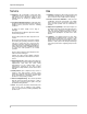
General Precautions NOTE This equipment has been certified and found to comply with the limits regulated by FCC, EMC, and LVD. Therefore, it is designated to provide reasonable protection against interference and will not cause interference with other appliance usage.
L19LD1600 Series Feature List L19LD1600 Series Feature List Monitor • Multiple easy to use control options: front panel buttons, Remote Control (included) and mouse (included). • On Screen Display: Date, Time, Sequence, Alarm status, Motion, Video loss, Camera title. • Multi-Lingual on screen display (English, French, Spanish, Chinese and Russian) • Industry standard BNC connector with 16 loop out ports.
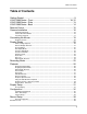
Table of Contents Table of Contents Getting Started .......................................................................................... 9 L19LD1600 Series - Front ................................................................. 10~12 L19LD1600 Series - Side ........................................................................ 13 L19LD1600 Series - Back ....................................................................... 14 Remote Control .......................................................
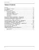
Table of Contents Table of Contents BACKUP ................................................................................................. 41 USB BACKUP SUBMENU ........................................................................................................ 41 Data Backup ........................................................................................... 41 EXTERNAL DEVICE ............................................................................... 42 TCP/IP SETUP - IP SETUP .........
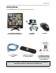
Getting Started Getting Started The L19LD1600 Series comes with the following components: LCD & DVR COMBO UNIT WITH INSTALLED 160 GB HDD 1 x 10’ ETHERNET CABLE 1 x POWER ADAPTOR 1 x REMOTE CONTROL 2 x AA BATTERIES 1 x MOUSE 1 x HARDWARE MANUAL 1 x SOFTWARE MANUAL 1 x QUICK START GUIDE 1 x SOFTWARE CD CHECK YOUR PACKAGE TO CONFIRM THAT YOU HAVE RECEIVED THE COMPLETE SYSTEM, INCLUDING ALL COMPONENTS SHOWN ABOVE.
L19LD1600 Series - Front L19LD1600 Series - Front 1 2 13 3 4 5 6 7 8 9 10 11 12 15 14 16 1. Mode 2. SEQ / Audio 3. PIP 4. Zoom 5. Freeze 6. Lock 7. PTZ 8. Next 9. Panic Record LED 10. LED Indicators 11. Monitor Power Button 12. Navigation Controls / Enter 13. Speaker 14. Channels / PTZ Controls 15. Playback Controls 16.JOG Shuttle 1.
L19LD1600 Series - Front L19LD1600 Series - Front 1 2 13 3 4 5 6 7 8 9 10 11 12 15 14 16 1. Mode 2. SEQ / Audio 3. PIP 4. Zoom 5. Freeze 6. Lock 7. PTZ 8. Next 9. Panic Record LED 10. LED Indicators 11. Monitor Power Button 12. Navigation Controls / Enter 13. Speaker 14. Channels / PTZ Controls 15. Playback Controls 16.JOG Shuttle 9. PANIC RECORD LED - Indicates that the system is in Panic (Manual Recording) Mode. Press the REC Button to exit. 10.
L19LD1600 Series - Front L19LD1600 Series - Front 1 2 13 3 4 5 6 7 8 9 10 11 12 15 14 16 1. Mode 2. SEQ / Audio 3. PIP 4. Zoom 5. Freeze 6. Lock 7. PTZ 8. Next 9. Panic Record LED 10. LED Indicators 11. Monitor Power Button 12. Navigation Controls / Enter 13. Speaker 14. Channels / PTZ Controls 15. Playback Controls 16.JOG Shuttle 14. CHANNEL BUTTONS / CONTROLS - Switches the full screen view between channels 1~16. The numbers are also used to enter the System Password.
L19LD1600 Series - Side 16. JOG SHUTTLE - Use to control video playback or adjust values in the System Menu: • Press the J SHUTTLE button to activate the Jog Shuttle. • The ACTIVE LED will flash indicating the Jog Shuttle is active. • In playback: Twist the inner rim to display video frame-by-frame. Twist the outer rim to play video in fast forward and fast reverse. Turn clockwise to play fast forward, and counterclockwise to play fast reverse. • Turn the Jog Shuttle to change values in System Setup.
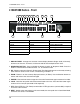
L19LD1600 Series - Back L19LD1600 Series - Back 1 2 4 3 8 5 6 9 7 10 1. VGA Out Port 2. Ethernet Port 3. Alarm Block 4. RS-232C Port 5. PS/2 Mouse Port 6. RCA Audio IN 7. RCA Audio Out 8. 16 Channel BNC IN 9. 16 Channel Loop OUT 10. Power Adaptor Port 11. System Power Switch 11 1. VGA OUT - The VGA Port is not functional on this model. 2. ETHERNET - Connects the System to a network router or other Ethernet Device 3. ALARM BLOCK - Controls Alarm IN devices. 4. .
Remote Control Remote Control Listed below is a quick reference for the Remote Control. 1. MENU: Press the Menu Button to display the System Configuration. 2. NUMBER KEYPAD: Use to switch between Cameras in live view mode. 3. SEQUENCE MODE: Changes the Monitor Display to Sequence through channels. 4. FREEZE: Freezes the onscreen image. 5. 4S BUTTON: Switches the screen view to Quad (4 Channel) View Mode. 6. 9S BUTTON: Switches the screen to view 9 Channel Split Screen. 7.
Camera Installation Camera Installation Before you install the camera, carefully plan where and how you will position the camera, and where you will route the cable that connects the camera to the System. Installation Warnings: • Select a location for the camera that provides a clear view of the area you want to monitor, which is free from dust, and is not in line-of-sight to a strong light source or direct sunlight.
Camera Installation Connecting Cameras 1. Connect the Female BNC end of the extension cable to the camera. Connect the male Power end of the extension cable to the camera. * Camera may not be exactly as shown. IMPORTANT NOTE: The ends of the extension cable are NOT the same - one end has a Male power port, and the other has a Female power port.
Camera Installation 2. Connect the Female end of the extension cable to an open BNC camera input on the back of the System. Connect the female Power end of the extension cable to the power adaptor. NOTE: To access the Connection Ports for the System, the monitor can be tilted forward (for easier access). * Camera may not be exactly as shown.
Connecting the Mouse Connecting the Mouse Connect the supplied mouse to the PS/2 Port on the back of the unit. PS/2 Connection - A mouse can be connected to the PS/2 Port on the back of the unit. • LEFT MOUSE BUTTON - Double click in Viewing Mode to display a camera in Full Screen. Used to adjust values in MENU Mode. • RIGHT MOUSE - Right click to open the Mouse Menu in Viewing Mode. Click the Right Button to exit a menu. • SCROLL WHEEL - Press and hold to exit the Mouse Menu.
Display Modes Playback Controls Click PLAY icon to switch to the playback interface. Click the SEARCH icon to switch back to the playback interface once playback has started. During Playback, the mouse buttons function as the following controls: Click the PTZ Button to enter PTZ Mode. Display Modes Initial Loading Sequence • Connect the POWER cable located on the back of the Observation System. The unit will automatically power on.
Display Modes General Display Overview 1.TIME - Displays the Current system time, or the recorded time in playback 2.DATE - Displays the Current system date, or the recorded date in playback 3.CAMERA TITLE - Displays the Camera title for the channel. The Camera title can be modified in the SYSTEM MENU ==> CONFIGURATION ==> CAMERA SETUP ==> CAMERA TITLE. 4.
Display Modes 7. NETWORK CONNECTION - The Network Indicators appear when a remote connection is made to the unit: • Indicates that there is no client connection. • Indicates that a client is connected to the system. 8.HDD RECORD / SEARCH PERCENTAGE - In LIVE Viewing mode, the percentage indicates the amount of HDD space used for recording. In PLAYBACK mode, the percentage indicates the amount of data played back. 9.
Display Modes Freeze in Split Mode In a split screen mode, press the FREEZE button then select a number button to choose the corresponding channel to freeze. Press the number again to cancel. Freeze in Full Mode In full screen mode, press the FREEZE button to freeze the channel, and press FREEZE again to cancel. Sequence View Sequence is only functional in full screen mode. Hold the SEQ Button for 2~3 seconds and enter sequence mode, and hold the SEQ Button again for 2~3 seconds to cancel it.
Display Modes Zoom View Select a channel to zoom, and press the ZOOM button to enlarge to 200%. Use the direction buttons to move the enlarged part. Use the direction buttons to choose an area and press ENTER to zoom. Press ZOOM again to cancel Key Lock After pressing the LOCK Button, the word LOCK will be displayed on screen, and all buttons are disabled at this time. To unlock, press and hold LOCK and enter Admin’s password. NOTE: Rebooting the DVR will not deactivate the LOCK function.
Recording Mode Recording Mode RECORDING MODE: • Indicates that the camera is recording in ALARM Mode. • Indicates that the camera is recording in MOTION DETECTION Mode. • Indicates that the camera is recording in CONTINUOUS Mode. NOTE: If the power is lost, the DVR will automatically resume the recording schedule after the power is back. NOTE: The system will stop recording when the following occur: • No camera video inputs are detected (the cameras are not attached to the system).
Playback Playback Starting Playback Mode Press the PLAY button on the front panel of the System, or click the onscreen PLAY icon to start playback, starting from the most recent recording. Stopping Playback Mode Press the STOP button on the front panel of the System, or click the onscreen STOP icon to stop the playback.
Playback Search Mode Press the SEARCH button on the front panel of the System, or click the onscreen SEARCH icon to search through previously recorded data. There are 3 modes for search: PERCENT BAR - Search by location a recording point on the bar. TIME/DATE SEARCH Search by appointing a time and date EVENT SEARCH - Search by Event list. Search Bar • Using Jog-shuttle or +/- keys to select the recording percentage of the search bar. • Press “ENTER “key to confirm and start the playback.
Playback Event List Search • TIME/DATE - Displays the event time and date. • CHANNEL - Displays the channel in which the event occurred. • EVENT - Displays the event type: z z z MOT - Motion detection LOS - Image lost ALM- Alarm trigger The system keeps up to 1000 events in its EVENT LIST. • Use the Left Mouse button to select the events, and use the Mouse wheel to switch pages. • Use the Arrow Buttons key to select events and the +/- key to switch pages.
Playback Using the inner circle of the Jog-shuttle to playback video in single frames. Turn clockwise for forward playback and turn counter-clockwise for reverse playback. Playback Controls - Remote Controller • UP Arrow: X times high-speed playback. • DOWN Arrow: X times low speed playback. • LEFT Arrow: Rewind. • RIGHT Arrow: Play To increase the speed: • REW key (High-speed backward playback) • FF key (High-speed forward Playback). • Press the keys repeatedly to adjust the speed rate.
System Setup and Navigation Press the MENU button on the Front panel or Remote, or click the onscreen MENU icon to log into system: System Menu - Overview 1. DISPLAY SETUP - Includes SCREEN SETUP for Live View and Playback. 2. CONFIGURATION - Includes HDD MANAGEMENT, TIME/DATE SETUP, CAMERA SETUP, INTERVAL SETUP, ALARM SETUP, BUZZER SETUP, PASSWORD SETUP, and SYSTEM INFORMATION. 3. RECORD SETUP - Includes RECORD CONFIGURATION and SCHEDULE SETUP. 4. BACK-UP - Backs up data to a memory stick or hard drive.
Display Setup Display Setup • TIME/DATE - Display (ON) or hide (OFF) the Time and Date on the screen. • ICON DISPLAY - Display (ON) or hide (OFF) the cue icons on the screen. • DVR STATUS - Display (ON) or hide (OFF) the recording status on the screen. • REC/PLAY BAR - Display (ON) or hide (OFF) the recording percentage of HDD. • CAMERA TITLE - Display (ON) or hide (OFF) the camera title. SCREEN DISPLAY: Controls the settings for the screen in Live and Playback Information display modes.
Configuration Configuration Hard Drive Management 1. HDD MANAGEMENT - Includes HDD SETUP (HDD Clear), and HDD INFORMATION. 2. CAMERA SETUP - Includes CAMERA TITLE and CAMERA COLOR SETUP. 3. MOTION SETUP - Includes SENSITIVITY, DURATION, DETECT CELL NUMBER. 4. ALARM SETUP - Set up the Alarm mode (N.C. or N.O) and the Alarm Output Duration. 5. INTERVAL SETUP - Set up the switch interval of the Full screen and the PIP screen. 6. TIME/DATE SETUP - Program the system date and time. 7. PASSWORD password.
Configuration SAVE DVR INFO: Once the ENTER button has been pressed on SAVE DVR INFO, the DVR information will be saved to HDD. • If the DVR information is saved properly, the message NOW CHANGE HDD DISK will be shown on the system. • Then power off the DVR and change with new HDD. • Be sure to write down the DVR information such as NTSC/PAL, MODEL name, Channel, HDD location (PORT 1, PORT2). When you want to retrieve the Data), you must do based on this DVR information.
Configuration NOTE: When a camera is in Covert Mode, no picture is displayed when in live viewing, however the camera images are still being recorded if Record is set to ON. • CHANNEL: Select the camera to be modified. MOTION SETUP: Program the motion parameters and the detection area CAMERA TITLE: Input the camera Title (max. 8 characters). • BRIGHTNESS: Adjust image brightness (-32~31). • CONTRAST: Adjust color contrast (-32~31). • SATURATION: Adjust color saturation (-32~31).
Configuration • STATUS: Indicates the camera status. ACTIVE means the video input status is normal, and LOSS means the video is lost. • COVERT: Set up the channel to be displayed or hidden when on the LIVE screen. MOTION MASK SETUP: Note: Please go to RECORD SETUP > SCHEDULE RECORD and change the record mode to MOTION to activate the MOTION settings. • REC: Set up the channel to be record. MOTION SETUP Users can configure the detection area for motion.
Configuration When the window is at the ALL OFF mode, you can activate the motion detection in the block. Alarm setup 5.BLOCK OFF: Block an area to deactivate the motion detection in the desired area. The setup steps are the same as BLOCK ON. If the window is at the ALL ON mode, you can deactivate the motion detection in the block you make. Interval setup 1. CHANNEL - Use [+] and [-] to select a channel. 2.ALARM INPUT- Set up the Alarm Input type. • N.
Configuration 1.CHANNEL - Use [+] and [-] to select a channel. 2. KEY BEEP - Turns on/off the beep while operating the front panel. 2. POPUP ON/OFF - Set up the POPUP function ON/OFF: Use [+] and [-] to select ON or OFF. When there is an event, the screen display will switch to a full screen of the corresponding channel. 3. VIDEO LOSS - Turns on/off the beep at the video loss. 3.EVENT - Use [+] and [-] to select the event type that will trigger the POPUP: 5.
Record Setup The three user levels have different authorities to operate the DVR. Record Setup System Information 1. RECORD CONFIGURATION - Set up overwrite, recording mode, picture quality, resolution, and recording speed. 2. SCHEDULE SETUP - Program the recording schedule. 3. HOLIDAY SETUP - Set up holidays, max. 100 days. Indicate the system information and its status.
Record Setup 1. OVERWRITE - Sets the Hard Drive to overwrite older data when full. • ON: When the hard drive is full, the system will overwrite the earliest recorded video. If the DVR has two hard drives, the overwriting starts from the Master drive. • OFF: The system stops recording when the hard drive is full. If the DVR has two hard drives, the system stops recording when the Master and Slave drive both are full. 2.
Record Setup Schedule record CLEAR ALL: Clear all the schedule settings Program a recording schedule throughout the week. NEXT: Go to the next page. The first page is from 00-12, and the second page is from 12-24. MODE: Press MODE to select an editing mode. Use the direction keys 3456 to move the cursor, and then press [+] and [-] to select a recording mode.
BACKUP 1. HDD - Indicates the start and the end recording date and time on the Hard Drive. 2. USB - Select a starting date and time for backup. Use Mouse wheel to change the value, then select the SIZE to choose a backup size. 3. SIZE - Insert the USB device, and the system will automatically check the disk size and display the available space onscreen. Use Mouse wheel to change the value. The system will automatically calculate the end date and time for backup.
EXTERNAL DEVICE EXTERNAL DEVICE 1. MAC ADDRESS - Displays the MAC address. MAC address cannot be changed and is unique to each system. 2. DHCP MODE - Set the DHCP mode to Manual or Automatic. • When DHCP is set to Automatic, the settings will be retrieved from the network router - and settings cannot be changed manually. • To turn off the DHCP automatic detection, set the DHCP MODE to DISABLE. 3. IP PORT - Manually Enter an IP Port number. The default port is 50000 1.
EXTERNAL DEVICE minute). Use the Mouse Wheel to change the value. PAN/TILT SETUP - COMMAND SETUP 4. REGISTER - Connect to the DDNS server and register the system information to the server. Click REGISTER to start the registration. 5. DNS STATUS - Indicates the current status of DDNS connection • IP ADDRESS: Indicates the current IP address recorded in the server • IP PORT: Indicates the current IP port recorded in the server.
EXTERNAL DEVICE PAN/TILT SETUP - SPEED SETUP (connected to the Alarm sensor block) pops up onscreen. 3. MOTION POP UP - Sets the MOTION detection pop-up to ON/OFF. 4. EVENT POP UP DURATION - If ALARM or MOTION events occur concurrently on several channels, then Channel 1 has first priority for onscreen POP UP. 1. PAN SPEED - Set the PANing speed (0 low ~ 7 high). 2. TILT SPEED - Set the TILTing speed (0 low ~ 7 high). 3. ZOOM SPEED - Set the speed of ZOOM IN/OUT (0 low ~ 7 high).
Observation System Specifications - Appendix #1 Observation System Specifications - Appendix #1 45
Observation System Specifications - Appendix #1 Observation System Specifications - Appendix #1 46
Full Connectivity Diagram - Appendix #2 Full Connectivity Diagram - Appendix #2 The following diagram outlines a general set of connections available with the Observation System.
Connecting a Slave (Spot-Out) Monitor - Appendix #3 Connecting a Slave (Spot-Out) Monitor - Appendix #3 Connections to a Slave Monitor / Spot-Out Monitor (not included with the System) can be made through the MONITOR OUT and/or the SPOT OUT ports on the back of the Observation System. A slave monitor can be a TV or Observation System Monitor. A Slave Monitor is used as a View Only device.
Connecting Motion / Alarm Device - Appendix #4 Connecting Motion / Alarm Device - Appendix #4 Motion detection and Alarm controls are enabled through the Menu system on the Observation System. Additional motion sensor devices can be connected to the system (Motion Sensors, Door/Window Sensors).
Connecting PTZ Cameras - Appendix #5 Connecting PTZ Cameras - Appendix #5 PTZ Cameras (not included with this system) can be connected to the PTZ Control Block on the back panel of the System. The PTZ Controls are enabled through the Menu system on the Observation System. Additional PTZ Cameras are available at http://www.lorexcctv.com Installing a PTZ (RS-485 Type) PTZ Camera: 1. Connect the Transmit Cable to the D+ port on the PTZ Control Block on the Observation System. 2.
Connecting to a PC using the Serial Port - Appendix #6 Connecting to a PC using the Serial Port - Appendix #6 The Observation System can be connected directly to a PC COM Port by using the Serial Port located on the back of the system. • To connect DVR to a PC, users must use a twisted RS232 cable (See below). • The RS232 settings (baudrate/ parity/ length/ stop bit) are NOT adjustable. The transmission baudrate is 19200bps, length 8 bits, stop bit 1, and the parity is none. ASCII-CODE is 1 BYTE.
Hard Drive Replacement - Appendix #7 Hard Drive Replacement - Appendix #7 The System comes with a pre-installed Hard Drive (located in the removable drive bay). This system will work with two (2) installed hard drives (at a max 750GB each). The steps below outline installing a drive in the removable bay - if installing an internal drive, it is recommended to speak with a PC Hardware Technician for assistance.
Hard Drive Replacement - Appendix #7 STEP 6: New Drive Format The New Hard Drive MUST be formatted. If a new HARD DRIVE is detected, the system will prompt you to FORMAT the drive. If you do not choose to format the HARD DRIVE, the drive will not be detected by the system. If you choose to FORMAT a drive in this way, the drive will no longer be readable by a regular PC. STEP 4: Reinsert the Cartridge Casing into the DVR NOTE: Do NOT turn off the System while the drive is formatting.
Play Only Mode - Appendix #8 Play Only Mode - Appendix #8 PLAY ONLY MODE can be used in the following situations: • When you need to playback a hard drive from another System • When you need to playback the video which you deleted by running HDD CLEAR Entering “PLAY ONLY MODE”: 1. Turn on the System. At the initial screen that says HDD DETECT, press [PLAY] and System enters “PLAY ONLY MODE”. 2. To exit PLAY ONLY MODE, reboot the System and DO NOT press PLAY at the initial screen.
Optional Accessories Optional Accessories The following accessories are available to add to your existing system: SLAVE / SPOT OUT MONITOR BNC TYPE CAMERAS EXTENSION CABLE Slave / Spot Out Monitors View selected Cameras on a second Monitor Additional BNC Type Cameras Extends the length between the CAMERA and MONITOR. Available in 60’ length. PTZ CAMERAS Accessory PTZ Cameras for additional view control.
LOREX PRODUCT LIMITED WARRANTY LOREX PRODUCT LIMITED WARRANTY LOREX warrants, to the original retail purchaser only (the “Purchaser”), that this item (the “Product”) is free from manufacturing defects in material and workmanship, provided the Product is used in normal conditions and is installed and used in strict accordance with the instructions contained in the Product's Owner's Manual.
LOREX PRODUCT LIMITED WARRANTY LOREX does not make any claims or warranties of any kind whatsoever regarding the Product's potential, ability or effectiveness to prevent minimize, or in any way affect personal or property damage or injury. LOREX is not responsible for any personal damage, loss or theft related to the Product or to its use for any harm, whether physical or mental related thereto.
It’s all on the web Product Information Specification Sheets User Manuals Software Upgrades Quick Start Guides Firmware Upgrades VISIT www.lorexcctv.com www.lorexcctv.com Lorex Technology Inc.