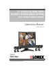
7" COLOR LCD DUAL QUAD SECURITY SURVEILLANCE SYSTEM WITH INTERNET REMOTE VIEWING Instruction Manual English Version 1.0 MODEL: SG17L7584 www.lorexcctv.com Copyright (c) 2006 LOREX Technology Inc.
Thank you for purchasing the IP enabled 17” LCD 2 Page/8 Channel Color Quad Observation system. Lorex is committed to providing our customers with a high quality, reliable security product. The IP enabled Observation system allows you to make an ethernet LAN connection from the monitor to a router for internet monitoring. With this 2 Page Quad system, you are capable of viewing up to 8 camera locations in real time (4 cameras per page).
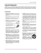
Important Safeguards Important Safeguards In addition to the careful attention devoted to quality standards in the manufacture process of your video product, safety is a major factor in the design of every instrument. However, safety is your responsibility too. This sheet lists important information that will help to assure your enjoyment and proper use of the video product and accessory equipment. Please read them carefully before operating and using your video product. Installation 1.
Important Safeguards Service Use 13. Servicing - Do not attempt to service this video equipment yourself as opening or removing covers may expose you to dangerous voltage or other hazards. Refer all servicing to qualified service personnel. 19. Cleaning - Unplug the video product from the wall outlet before cleaning. Do not use liquid cleaners or aerosol cleaners. Use a damp cloth for cleaning. 14.
General Precautions NOTE This equipment has been certified and found to comply with the limits regulated by FCC, EMC, and LVD. Therefore, it is designated to provide reasonable protection against interference and will not cause interference with other appliance usage.
Observation System Features Observation System Features • High Resolution 17" LCD Monitor with Network Interface for Remote Viewing over the internet* • Ultra Sharp image reproduction with High Contrast Ratio • Dual Quad Technology allows for viewing of up to 8 cameras • Wide Viewing Angle with On-screen viewing of date, time and camera title • Fast Response Time (prevents ghosting) • Slim Space Saving Design • Convenient cable channel for running wires • Flexible stand allows for height adjustment and ver
Table of Contents Table of Contents Getting Started .......................................................................................... 8 SG17L7584 - Front - Primary Function Buttons ................................... 9-12 SG17L7584 - Front - Secondary Function Buttons ................................. 13 SG17L7584 - Back ............................................................................. 14-15 Remote Control ................................................................................
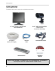
Getting Started Getting Started The SG17L7584 system comes with the following components: 17” Color 2 Page / 8 Channel Dual Quad LCD Monitor 4 x Camera Cables (57’ Length) Ethernet Cable Remote Control 4 x 1/4” CCD Color IR Day/Night Cameras (with Removable Sunshade) Standard Power Cable NetViewer Software CHECK YOUR PACKAGE TO CONFIRM THAT YOU HAVE RECEIVED THE COMPLETE SYSTEM, INCLUDING ALL COMPONENTS SHOWN ABOVE.
SG17L7584 - Front - Primary Function Buttons SG17L7584 - Front - Primary Function Buttons 1 2 3 4 15 5 16 17 6 7 8 9 10 18 19 20 21 22 11 12 13 14 1. FN (FUNCTION) BUTTON - When this button is pressed, the LED below the button will turn ON indicating that secondary function of the front panel buttons can be activated. To de-activate the secondary function for the buttons (and reactivate the primary functions), press the button [FN] button again and the LED will turn off. 2.
SG17L7584 - Front - Primary Function Buttons 4 5 6 4. FRZ ALL BUTTON - The function of the FRZ ALL (Freeze All) button is to digitally freeze the image that is being displayed on the monitor. To freeze an image: • Press the [FRZ] button while viewing a FULL SCREEN single camera in live video. This will freeze the camera image being viewed. • Pressing the [FRZ] button while in Quad mode. This will freeze all four cameras displayed on the monitor. An "F" will appear in the On-Screen Display.
SG17L7584 - Front - Primary Function Buttons 7 8 9 7. ZOOM BUTTON - This monitor is equipped with 2 times digital ZOOM. To utilize this feature proceed as follows: • Set the monitor to full screen mode or Quad mode for the desired channel • Press the ZOOM button. ZOOM mode is now active • Use the Navigation Buttons [ ÇÈÅÆ ] keys to move the area being captured in 2x ZOOM MODE. • To exit ZOOM MODE, press the ZOOM button again. 8.
SG17L7584 - Front - Primary Function Buttons 10 11 12 13 14 10. PIP POP BUTTON - Display a main camera image with secondary camera sub-images: • PIP (Picture In Picture) allows you to view three locations simultaneously, one being the main channel, the others being viewed as small images on the screen. To view detailed settings, see Main Menu Controls on Page 25. DUAL PIP • POP (Picture on Picture) divides the screen into 4 screens, with the main channel occupying two-thirds of the screen.
SG17L7584 - Front - Secondary Function Buttons SG17L7584 - Front - Secondary Function Buttons 15 16 17 18 19 20 21 22 15. ALRS (ALARM RESET) BUTTON - To reset an alarm when it is active, press the [FN] button to activate the secondary functions (note that the LED below the button will turn on), and press the ALRS button. The alarm will be reset. 16.
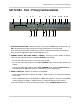
SG17L7584 - Back SG17L7584 - Back 1 2 3 4 5 6 7 1. RCA AUDIO INPUTS - Channel 1-8 Audio inputs (for non-DIN type cameras with standard RCA Audio output). 2. BNC VIDEO INPUTS - Channel 1-8 camera inputs (used to connect Cameras with BNC connection type), or can be used for Looping Video Output to a DVR NOTE: When DIN type cameras are connected on a channel, the BNC CONNECORS serve as LOOPING VIDEO OUTPUTS, and will send video to another device (such as a DVR or SLAVE MONITOR). 3.
SG17L7584 - Back SG17L7584 - Back Additional controls can be accessed by tilting the monitor forward. 1 2 3 1. AC INPUT - Connect the AC power (using the power cord provided with the unit) from the monitor to an electrical outlet 2. POWER SWITCH - This button controls power to the entire unit. Depress the side with the ‘I" to turn power ON. Depress the other side to turn the unit OFF 3. ETHERNET PORT - Connects the monitor to a router for connection to the internet.
Remote Control Remote Control Listed below is a quick reference for the Remote Control. For details on specific features, refer to the SG17L7584 - Primary / Secondary Buttons on Pages 10-14.
Installing Cameras Installing Cameras The SG17L7584 Observation System includes 4 - 1/4” CCD Color IR Day/Night Indoor/Outdoor Cameras* INFRA-RED LEDs Provides illumination for low light conditions CAMERA LENS Delivers CCD Color image to the Observation System using a 6mm lens MICROPHONE Picks up sound near the camera and transmits to the Observation System INPUT CABLE (BACK) Delivers Video / Audio / Power from the Observation System to the Camera BRACKET Metal bracket connects to the Camera for mount
Connecting Cameras Connecting Cameras The SG17L7584 Observation System includes 4 x 1/4” Color CCD DIN Cameras. Additional cameras can be added to the 4 additional camera inputs using the DIN or BNC ports. DIN Connected Cameras 4 x 1/4” COLOR CCD DIN cameras are included with the Observation System. These cameras have a single cable, and receive power directly from the Observation System.
Monitor Features Monitor Features The SG17L7584 Observation System has adjustable tilt and height positioning. The height can be adjusted using the thumbscrews at the base. • Loosen the thumbscrews (located on the lower left and right sides of the base) • Adjust the Monitor to the desired height • Tighten the screw to hold the Monitor positioning Thumbscrews The Monitor can be tilted at a 45° angle (where the base meets the monitor).
Cable Channel Cable Channel The SG17L7584 Observation System comes with a built in cable channel to easily organize and conceal wiring. 1. Remove the Cable Channel Cover. 2. Connect the Power Cable, Cameras, Ethernet Cable and any Alarm Devices to the System by running the cables through the hole in the stand before connecting to the Observation System. 3. Once all cables have been connected to the System, replace the Cable Channel cover.
Main Menu Control Main Menu Control Enter the MENU screen by pressing the MENU button. Scroll through the 9 options by pressing the UP and DOWN buttons. To enter a sub-menu, navigate to the option and press the OK button. To exit a SUBMENU, select the RETURN option (and press the OK button) which takes you back to the MAIN MENU. To exit the MAIN MENU, select the EXIT option from the sub-menu (and press the OK button).
Time / Date Set Time / Date Set This submenu allows you to change the TIME and DATE displayed on the monitor (On Screen Display), and recorded through an optional DVR / VCR. 1. DISP MON - Display the DATE / TIME on the monitor screen. Available options include Y and N. To set this feature, navigate by pressing the K and L buttons to highlight, and press the OK button to switch between Y and N. 2. DISP REC - Display the DATE / TIME on the DVR recording. Available options include Y and N.
Sequence Set Sequence Set This submenu allows you to change the length of time a camera is displayed while the SEQUENCE (SEQ) feature is enabled. When in SEQUENCE mode, the observation monitor cycles through available cameras in the sequence shown below. NOTE: If a camera is set to 0 SEC, it will be skipped in the AUTO SEQUENCING. Any channel without an attached camera will be skipped automatically. 1. QUAD-A - Shows cameras 1 - 4 in QUAD screen mode.
PIP/POP Set PIP/POP Set This submenu allows you to change the settings for PIP (Picture IN Picture) and POP (Picture ON Picture). PIP displays small viewing screen(s) superimposed onto the larger main viewing screen,. POP displays small viewing screen(s) along the top or bottom of the larger main viewing screen. 1. PIP SEQUENCE - Switch between SUB and MAIN views. Navigate by pressing the K and L buttons to highlight, and press the OK button to change the PIP sequence mode 2.
Title Set 4. RETURN - Return to the MAIN MENU. Navigate by pressing the K and L buttons to highlight, and press the OK button to select 5. EXIT - Return to the camera view. Navigate by pressing the K and L buttons to highlight, and press the OK button to select [PIP/POP SET] PIP SEQUENCE PIP POSITION POP POSITION RETURN EXIT : : : : : [SUB] [00] [01] [ ] [ ] Title Set This submenu allows you to change the displayed description of the camera (8 character max.).
Alarm Set Alarm Set This submenu allows you to configure the ALARM alert type and duration.This alarm type is used in conjunction with external alarm input terminals. PIR cameras are offered by LOREX, but are not included with this system. 1. ALARM - Configures the ALARM type for an alarm event.
Motion Set Motion Set This submenu allows you to change the configurations for MOTION detection, using the monitors built-in Pixel Based Motion Detection. 1. MOTION - Sets the motion detection alarm mode. Navigate by pressing the K and L buttons to highlight, and press the OK button to switch between MOTION alarm modes: • OFF - Motion Detection is disabled • OSD (On Screen Display) - Visual alert only [MD] • OSD + BUZZER - Both Visual and Audible alerts 2.
Motion Set 4. AREA - Sets the area for motion detection. Navigate by pressing the K and L buttons to highlight, and press the OK button to set the MOTION detection area. Selections include: [01] [02] [03] [04] [05] [00] (FULL SCREEN) 5. RETURN - Return to the MAIN MENU. Navigate by pressing the K and L buttons to highlight, and press the OK button to select 6. EXIT - Return to the camera view.
System Set System Set This submenu allows you to change the general preferences for the OBSERVATION SYSTEM. 1. KEY BUZZER - Sets the audible BUZZER that can be heard when pressing any key to ON or OFF. Navigate by pressing the K and L buttons to highlight, and press the OK button to select Y or N. 2. LOSS BUZZER - Sets the audible BUZZER ON/ OFF when a loss of channel signal is detected. Navigate by pressing the K and L buttons to highlight, and press the OK button to accept 3.
System Set 7. PAN/TILT - Adjust the Pan / Tilt of the camera (PTZ cameras only). Select Y if a PTZ camera is connected. 8. ALARM OUT - Set to N/O (Normally Open) or set to N/C (Normally Closed). 9. DEFAULT SET - Set to Y to reset the unit to factory defaults upon exiting the menu 10. RETURN - Return to the MAIN MENU. Navigate by pressing the K and L buttons to highlight, and press the OK button to select 11. EXIT - Return to the camera view.
Monitor Set Monitor Set This submenu allows you to change the picture settings for the OBSERVATION SYSTEM MONITOR. 1. CONTRAST - Adjust the image contrast. Navigate by pressing the K and L buttons to highlight, and press the OK button to select. Press the K and L buttons to change the CONTRAST (maximum of 63). Press OK to accept the changes. 2. BRIGHT - Adjust the image brightness. Navigate by pressing the K and L buttons to highlight, and press the OK button to select.
NetViewer - Installation Requirements NetViewer - Installation Requirements The NetViewer software (included with the Observation System) has the following installation requirements. Minimum System Requirements: Operating System Windows 2000 Windows XP Home Edition Windows XP Professional Processor .Pentium 4 - 1.5 GHz Processor (or equivalent) Memory 256 MB RAM Hard Drive 50 MB - Installation space required * Additional Hard Drive space required for recording.
Network Connectivity Network Connectivity The SG17L7584 Observation System can be remotely controlled using your existing network and the provided NetViewer software. 1. Connect the Observation System to the Router using the supplied Ethernet Cable. Power the Observation unit on. You may need to tilt the monitor forward to access the Ethernet Port. OBSERVATION SYSTEM NOTE: The Observation System must be connected to the router prior to powering on the system.
Setting Up Your DDNS Account Setting Up Your DDNS Account Lorex offers a free DDNS server for use with your System. A DDNS account allows you to set up a web site address that points back to your Local Network. The following outlines how to set up your free DNS account. 1. Navigate to http://DDNS.strategicvista.net 2. Select the Create Account option from the list on the left side of the screen. 3.
Setting Up Your DDNS Account 4. Complete the System Information fields as follows: • Product License: Select your product model from the Product License drop down menu • - : Locate the MAC address of your (recorded while loading the System) • URL Request: Choose a URL for your DDNS connection (i.e. your name, your company or business name, or anything of your choice.) NOTE: The URL request must not exceed 8 CHARACTERS 5.
Using the Lorex IPEdit Application Using the Lorex IPEdit Application The Lorex IP Edit application allows you to find and change the details of your Lorex network device (i.e.. Observation System, DVR, or IP Camera). 1. Connect the LAN output of the OBSERVATION SYSTEM to your router using the provided Ethernet cable. 2. Download the Lorex IPEdit application from the http://www.lorexcctv.com website 3. Double -click the application to run 4. A list of all detected Lorex Network Devices will be shown.
Router Port Forwarding Router Port Forwarding How do I enable Port Forwarding on my Router? You will need to enable port forwarding on your Router to allow for external communications with your Observation System. Computers, Observation Systems, and other devices inside your network can only communicate directly with each other within the internal network. Computers and systems outside your network cannot directly communicate with these devices.
Troubleshooting Troubleshooting When a malfunction occurs, it may not be serious and can be corrected easily. The following describes the most common problems and solutions.
Troubleshooting Problem: The image on the Observation System is too dark or too bright Check: • Adjust the CONTRAST and BRIGHTNESS of the unit (Refer to the Menu section) Problem: The image on the Observation System appears, but does not have sound Check: • Check the VOLUME • Check the CAMERA connection to the Observation System • Confirm that the Camera has sound capabilities (Refer to the manual for the camera model for further information on the Camera functionality) Problem: The picture on the Observ
Observation System Specifications - Appendix #1 Observation System Specifications - Appendix #1 Display 17” TFT LCD Pixels (H x V) 1280 H x 1024 V Pixel Arrangement RGB Vertical Strip Pixel Pitch 0.264 x 0.
Camera Specifications - Appendix #2 Camera Specifications - Appendix #2 Image Device 1/4" Interline transfer type color CCD Effective Pixels 512 H x 492 V (252k PIXELS) Scanning System 525 Lines 2:1 Interlace Resolution Horizontal 350 TV lines Shutter Speed 1/60 ~ 1/10,000 sec. S/N Ratio More than 48dB (AGC off) Sync. System Internal Min. Illumination 1.0 Lux (without LED) / 0.1 Lux (with LED) White Balance AWB Video Output VBS 1.
Connecting to a Single Channel DVR / VCR - Appendix #3 Connecting to a Single Channel DVR / VCR - Appendix #3 The SG17L7584 Observation System can be used with a Single Channel DVR or VCR unit (not included) 1. Connect the Video cable from the VIDEO OUT port on the Observation System to the VIDEO IN port on the DVR or VCR Unit OBSERVATION SYSTEM 2.
Connecting to a Multi-Channel DVR - Appendix #4 Connecting to a Multi-Channel DVR - Appendix #4 The SG17L7584 Observation System can be used with a Multi-Channel DVR (not included). A Multi-Channel DVR enables you to record multiple video streams with a single device NOTE: The CH1 - CH8 BNC Video inputs serve as Looping Video Outputs by individual channels when a DIN camera is connected to the associated channel. OBSERVATION SYSTEM 1.
Connecting a Slave Monitor - Appendix #5 Connecting a Slave Monitor - Appendix #5 Connections to a Slave Monitor (not included) can be made through the SLAVE OUT ports on the back of the Observation System A Slave Monitor is used as a View Only device. A Slave Monitor can only display camera data as it is shown on-screen on the Observation System. OBSERVATION SYSTEM Specific controls for the Observation System are configured through the Menu Options 1.
Connecting Motion / Alarm Device - Appendix #6 Connecting Motion / Alarm Device - Appendix #6 Motion detection and Alarm controls are enabled through the Menu system on the Observation System. Additional motion sensor devices can be connected to the system (Motion Sensors, Door/Window Sensors).
Full Connectivity Diagram - Appendix #7 Full Connectivity Diagram - Appendix #7 The following diagram outlines a general set of connections available with the SG17L7584 Observation System.
Optional Accessories Optional Accessories The following accessories are available to add to your existing system CABLE DVR UNIT QUAD LOOPING OUTPUT CABLE Extends the length between the CAMERA and MONITOR.
Optional Accessories 48
It’s all on the web Product Information Specification Sheets User Manuals Software Upgrades Quick Start Guides Firmware Upgrades VISIT www.lorexcctv.com wwwlorexcctv.com Strategic Vista International Inc.