SECURITY CAMERA INSTRUCTION MANUAL ENGLISH VERSION 1.0 LBC5451 www.lorextechnology.
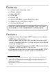
Contents • 1x Camera and mounting stand • 1x Power adapter • 1x Mounting kit • 1x Allen key • 1x Screw cap • 1x 60 ft. (18m) BNC / power extension cable • 1x BNC Female / RCA Male adapter • 1x Instruction Manual CHECK YOUR PACKAGE TO CONFIRM THAT YOU HAVE RECEIVED ALL THE COMPONENTS SHOWN ABOVE. Features • High resolution Sony Super HAD™ image sensor delivers 540TV lines of resolution.
Safety Instructions • Read this guide carefully and keep it for future reference. • Follow all instructions for safe use of the product and handle with care. • Use the camera within given temperature, humidity, and voltage levels noted in the Technical Specifications. • Do not disassemble the camera. • Do not point the camera directly towards the sun or a source of intense light. • Use only the supplied regulated power supply.
TABLE OF CONTENTS 1. Camera Overview . . . . . . . . . . . . . . . . . . . . . . 1 2. Night Vision Features . . . . . . . . . . . . . . . . . . 2 2.1 Night Vision . . . . . . . . . . . . . . . . . . . . . . . . . . . . . . . . . . . . . . .2 2.2 Motion Detection / White Light LEDs . . . . . . . . . . . . . . . . . . .2 3. Installation Tips . . . . . . . . . . . . . . . . . . . . . . . 4 3.1 Suggested Install Locations . . . . . . . . . . . . . . . . . . . . . . . . . .5 4. Installing the Camera . . . . .
iv
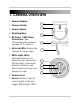
1. CAMERA OVERVIEW 1 Camera Module 1 2 Camera Holder 2 3 Camera Mount 4 Mounting Base 5 DC Power / BNC Video Connectors: See “Connecting the Camera” on page 12 for details. 6 Infrared LEDs: Enable the camera to see at night. 7 White Light LEDs: Automatically turn on when motion is detected (during night vision only) to deter criminals and allow camera to view color images at night 3 4 5 6 7 8 9 8 Camera Lens 9 Sensor: Detects light to control night vision and trigger White Light LEDs.
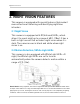
Night Vision Features 2. NIGHT VISION FEATURES This camera is equipped with special features that make it more effective at deterring and identifying nighttime intruders. 2.1 Night Vision This camera is equipped with IR (Infrared) LEDs, which allow it to see at night up to a range of 60 ft. (18m). It has a built-in light sensor that activates night vision when it is dark. The camera sees in black and white when night vision is on. 2.
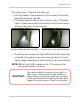
Night Vision Features This helps deter / identify intruders by: • Alerting them to the presence of the camera, after they have already been spotted. • Providing a better view of the intruder’s face. The white lights on the camera turn on instantly to surprise intruders, drawing their eyes to the camera. Typical night-vision cameras may be overlooked by intruders White Light LEDs draw attention to help identify faces • Providing color images at night.
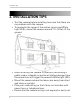
Installation Tips 3. INSTALLATION TIPS • Test the camera before installing to ensure that there are no problems with the camera. • To maximize the range of the motion sensor and White Light LEDs, mount the camera around 7 ft. (2.2m) off the ground. • Avoid installing the camera in locations overlooking a public road or sidewalk, as motion or lighting changes from these locations will trigger the camera’s White Light LEDs. • Mount the camera where the lenses are away from direct and intense sunlight.
Installation Tips • Adjust the camera angle so that it provides a satisfactory view of the area you would like to monitor. • In "high-risk" locations, have multiple cameras point in the same area. This provides camera redundancy if a camera malfunctions, or if a vandal attempts to damage the camera. • Mount the camera in an area that is visible but out of reach. 3.
Installing the Camera 4. INSTALLING THE CAMERA 4.1 Before Installing the Camera Decide if you are going to run the cables through the wall / ceiling (drilling required) or along the wall / ceiling. • If you are running the cables through the wall / ceiling, connect the power and BNC video cables to the camera before installing. See “Connecting the Camera” on page 12 for details.
Installing the Camera 2 Run the cable through the base (Figure 3) and secure it by pushing the rubber bumper on the cable through the slot on the base (Figure 4). This prevents the camera from falling during installation. • If you are running the cables along the wall / ceiling, make sure to run the cable through the cable notch on the base. This will keep the camera base flush to the wall / ceiling when mounted.
Installing the Camera 3 Mount the base to the desired surface using the included screws. NOTE: If mounting to drywall, use the included drywall plugs. NOTE: Camera hangs down from base during mounting. 4 Attach the camera to the base. Align the base screws with the slots on the base, slide the camera onto the base, and twist.
Installing the Camera 5 Adjust the camera position as needed (see “Positioning” on page 10 for details). NOTE: Ensure that the sensor is directly below the camera lens (in the 6 o‘clock position) or the image will appear rotated. 6 Tighten the screws to secure the camera in position and snap the screw cap over the arm screw. Correct sensor position Arm screw Base screws Screw cap Lens screws Do not over-tighten the screws, as this may crack the camera or base.
Positioning 5. POSITIONING The camera offers flexible positioning, allowing you to manually adjust the camera for wall or ceiling installation. NOTE: To maximize the range of the motion sensor and White Light LEDs, it is recommended to mount the camera around 7 ft. (2.2m) off the ground. Tilt the camera to adjust the angle. Loosen the screws on both sides of the base and twist the camera to adjust the camera direction. Do not over-tighten the screws, as this may crack the camera or base.
Positioning Loosen the screws on both sides of the camera module and twist to adjust the sensor position. The camera module can only twist one full rotation in either direction. Do not force the lens, as this can break the camera. Camera module screws Make sure that the sensor is directly below the camera lens (in the 6 o‘clock position). Otherwise, the image will appear rotated. Correct sensor position Do not over-tighten the screws, as this may crack the camera or base.
Connecting the Camera 6. CONNECTING THE CAMERA 1 2 BNC extension cable Male power BNC connector To Camera: Female power To Monitor / DVR: 1 Connect the male power connector on the BNC extension cable with the female power connector on the camera. • Connect the BNC connector on the extension cable to the camera. 2 Connect the female power connector on the extension cable to the power adapter. • Connect the BNC connector on the extension cable to your monitor or DVR.
Connecting the Camera 6.1 BNC to RCA Adapter (Optional) DVR / CCTV MONITOR Video IN TV / VCR Video IN BNC to RCA Adapter Attach the included BNC to RCA adapter to connect the extension cable to RCA inputs (i.e. for a TV connection). 6.
Technical Specifications 7. TECHNICAL SPECIFICATIONS 14 Image Sensor 1/3" Sony Super HAD™ II Video Format NTSC Effective Pixels H:768 V:494 Resolution 540 TV Lines Scan System 2:1 Interlace Sync System Internal S / N Ratio 48 dB (AGC OFF) Iris AES AES Shutter Speed NTSC: (1/60~1/100,000 sec.) Min. Illumination 0.2 Lux without IR LED 0 Lux with IR LED Video Output Composite 1.0Vpp @ 75ohm Lens / Lens Type 4.3mm F2.
Technical Specifications Power Requirement 12V DC ±10% Power Consumption Max. 300mA (w/White Light LEDs) Operating Temp. Range 14° ~ 122° F / -10 ~ 50° C Operating Humidity Range < 80% RH Environmental Rating2 IP 67 Weight (including stand) 0.75 lbs. / 0.34kg 1. IR Illumination Range under ideal conditions. Objects at or beyond this range may be partially or completely obscured, depending on the camera application. 2. Not intended for submersion in water.
Cable Extension Options 8. CABLE EXTENSION OPTIONS You can extend the cable run for your camera up to 300 ft. depending on the cable type used. See table below: Option Cable Type Max Cable Run Distance Max. # of Extensions 1 Regular BNC (supplied with camera) 180 ft. / 55m 3 2 'RG59' or 'Coax' or 'Coaxial' BNC (sold separately) 300 ft. / 92m 5 3 Lorex Universal Cable (sold separately) 300 ft. / 92m 3 Notes: 1 For optimal performance, consider using option 2 or 3.
Troubleshooting 9. TROUBLESHOOTING Problem Solution No Picture / Signal • Ensure your TV is on the correct input channel. Common terms of an input channel: INPUT, AV CHANNEL, LINE1, LINE2, AUX. • If your camera is connected to a VCR / DVR, ensure it is properly connected to your TV / Monitor. • Ensure connections are properly connected. • Ensure the camera power supply is plugged in. Picture is too bright • Ensure your camera isn’t pointed directly at a source of light (e.g. sun or spot light).
Troubleshooting 18 Problem Solution Picture is not clear • Check the camera lens for dust, dirt, and spiderwebs. Clean the lens with a soft, clean cloth. • Make sure that the cable run is within the limitations specified in the section 'Cable Extension Options'. Night vision is not working • The night vision activates when light levels drop. The area may have too much light. White Light LEDs do not turn on • Motion detection range is limited to 9 ft. (3m).
LBC5451 Ver si o n 1 .0 www.lorextechnology.com Copyright © 2011 Lorex Technology Inc.