
Owner's Manual


Table Of Contents
- NVR Overview
- Basic Setup
- Step 1: Connect the IP Cameras
- Step 2: Connect the Mouse
- Step 3: Connect the Ethernet Cable
- Step 4: Connect the Monitor
- Step 5: Connect the Power Adapter and Power on the NVR
- Step 6: Verify Camera Image
- Step 7: Set the Time
- Default System Password & Port Numbers
- Quick Access to System Information
- Installing Cameras
- Mouse Control
- Remote Control
- Using the On-Screen Display
- Setting the Date and Time
- Recording
- Playback
- Backing Up Video
- Managing Passwords
- Using the Main Menu
- Manual
- HDD
- Record
- Camera
- Configuration
- Maintenance
- Shutdown
- Setting up your NVR for Remote Connectivity
- Client Software for PC
- Control Panel
- Main View
- Video Player
- E-Map
- Event Search
- Remote Playback
- Add Camera
- Local Log Search
- Account Management
- Device Management
- Configuring an NVR Through Device Management
- Camera Settings
- Adjusting Picture Settings
- Configuring Video Quality
- Configuring Camera Recording Schedules
- Configuring the Camera Video Display (OSD) and Privacy Masks
- Configuring Motion Detection Settings
- Configuring Tampering Alarm Settings
- Configuring Video Loss Alarms
- PTZ Control (Not Supported)
- Network Connection (Not Supported)
- System Configuration
- Connecting to your NVR Using a Web Browser
- Mobile Apps: Accessing your NVR Using a Mobile Device
- Appendix A: System Specifications
- Appendix B: Installing or Replacing the Hard Drive
- Troubleshooting
- Getting Started
Thank you for purchasing the Lorex Network Video Surveillance Recorder.
This manual refers to the following models:
• LNR240 (4-channel)
• LNR280 (8-channel)
For the latest online manual, downloads and product updates, and to learn about our
complete line of accessory products, please visit our website at:
www.lorextechnology.com
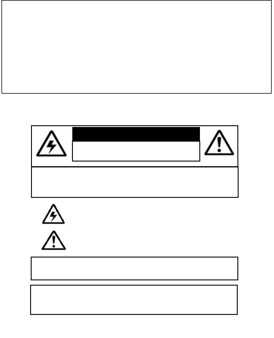
CAUTION
RISK OF ELECTRIC SHOCK
DO NOT OPEN
CAUTION: TO REDUCE THE RICK OF ELECTRIC SHOCK DO NOT
REMOVE COVER. NO USER SERVICABLE PARTS INSIDE.
REFER SERVICING TO QUALIFIED SERVICE PERSONNEL.
The lightning flash with arrowhead symbol, within an equilateral
triangle, is intended to alert the user to the presence of uninsulated
"dangerous voltage" within the products ' enclosure that may be of
sufficient magnitude to constitute a risk of electric shock.
The exclamation point within an equilateral triangle is intended to
alert the user to the presence of important operating and
maintenance (servicing) instructions in the literature accompanying
the appliance.
WARNING: TO PREVENT FIRE OR SHOCK HAZARD, DO NOT
EXPOSE THIS UNIT TO RAIN OR MOISTURE.
CAUTION: TO PREVENT ELECTRIC SHOCK, MATCH WIDE BLADE
OF THE PLUG TO THE WIDE SLOT AND FULLY INSERT.