TRIPLEX NETWORK DIGITAL VIDEO RECORDER Instruction Manual English Version1.0 MODEL: L224 Series www.lorexcctv.com Copyright © 2006 Lorex Technology Inc.
Thank you for purchasing the L224 Series Triplex Network Digital Video Recorder. Lorex is committed to providing our customers with a high quality, reliable security product. The L224 Series DVR allows for Triplex Functionality – Record, View and Search for recoded data simultaneously, and supports up to a 500 GB Hard Drive. The system can be viewed and controlled over the internet from a remote location with trouble free access via the Free DDNS Service.
IMPORTANT SAFEGUARDS
IMPORTANT SAFEGUARDS
IMPORTANT SAFEGUARDS
TABLE OF CONTENTS PARTS AND FEATURES 1.1 1.2 1.3 1.4 1.
1.
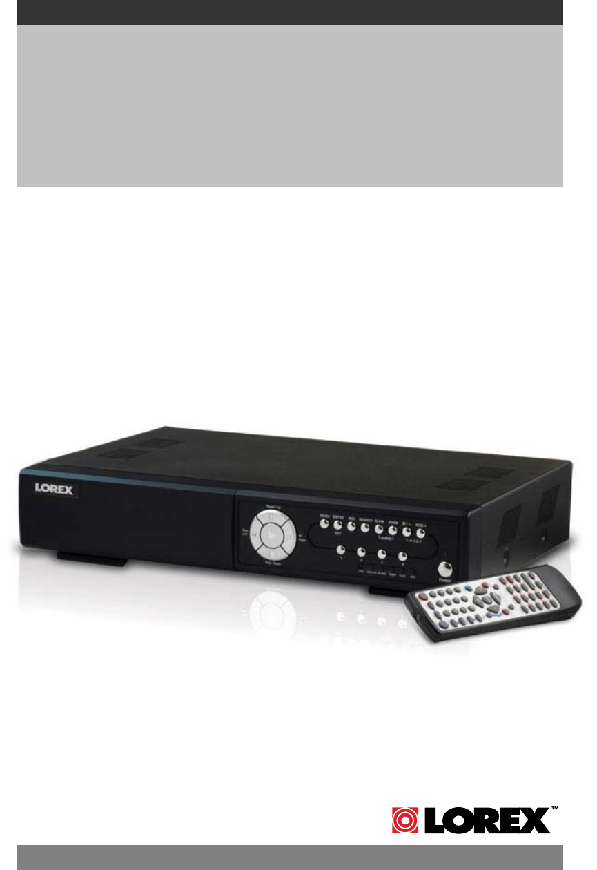
1.2 CONTENTS L224 Series DVR with Remote Control Power Adapter Manual and Software CD CHECK YOUR PACKAGE TO CONFIRM THAT YOU HAVE RECEIVED THE COMPLETE SYSTEM, INCLUDING ALL COMPONENTS SHOWN ABOVE.
1.3 SPECIFICATIONS Video System NTSC / PAL (switchable) Video Compression Format Frame: MJPEG ; CIF: MPEG4 Video Input 4 Channels. Composite video signal 1 Vp-p 75Ω BNC Video Loop Out 4 Channels.
1.3 SPECIFICATIONS Specification Continued… Web Transmitting Compression Format Ethernet Web Interface Remote Alarm Notification Network Connection Motion JPEG 10/100 Base-T.
1.
1.4 FRONT PANEL 1) “LED LIGHT” : HDD: HDD is reading or recording HDD Full: HDD is full. ALARM: Once the alarm is triggered TIMER: When timer recording is turned on PLAY: Under playing status REC: Under recording status 2) “MENU” : Press “MENU” button to enter the main menu. 3) “ENTER” / “SET” : Press “ENTER” button to confirm the setting. Press “SET” to change the position of the channel display. Press “▲▼◄►“ to select the channel which you would like to change.
1.4 FRONT PANEL 10) “CH1 ” “CH2 ” “CH3 ” “CH4 ” : Press “1 ” “2 ” “3 ” “4 ” buttons to select the channel to display. 11) “REC” : Press “REC” button to activate the manual recording. 12) “ “ or “PLAY” : Press this button to playback the recorded data. 13) “UP / PAUSE , DOWN / STOP, LEFT / FAST REWIND, RIGHT / FAST FORWARD“ : Press “▲▼◄►“ to move the cursor up / down / left / right. Under the playback mode, press “ “ button to pause playback. Under the playback mode, press “ ■ “ button to stop playback.
1.5 REAR PANEL 2 1 LOOP INPUT LOOP 1 INPUT 2 LOOP INPUT 3 LOOP INPUT 3 4 MONITOR CALL 4 5 6 IN OUT 12 USB LINK ACT. D/ V 7 IR EXTERNAL I/O 13 LAN 8 9 DC 19V 10 11 1) 75Ω / HI-IMPEDANCE: When using Loop function, please switch to HI-IMPEDANCE. When you don’t use Loop function, please switch to 75Ω. 2) VIDEO INPUT (CHANNEL 1 - 4): Connect to video sources, such as cameras. LOOP (CHANNEL 1 - 4): Video output. 3) MONITOR: Connect to Main monitor.
GETTING STARTED 2.1 GETTING STARTED Connect all the devices: 1) Install HDD: The HDD must be installed before the DVR is turned on. Please refer to Appendix #1 for HDD installation instructions. 2) Connect cameras, monitors and external devices. Please refer to the section “1.5 REAR PANEL” for connection, and Appendix#2 for pin configurations of the external I/O port. NOTE: Be sure the cameras are connected and power-supplied before the DVR is powered on.
BASIC OPERATION 3.1 RECORDING The DVR offers three recording modes, manual record, event record and timer record. If power is off accidentally, recorded video files will still be still stored in the HDD. DVR will return to the original recording status after power is on again. 1) MANUAL RECORDING (continuous recording) : Recording is initiated by manually pressing the “REC” button, indicated by the sign “●” on the screen.
3.2 PLAYBACK Press “ ” or “PLAY” button and the DVR will display the last recorded video. 1) FAST FORWARD (F.F. ) & FAST REWIND (REW): You can increase the speed for fast forward and rewind on the DVR. In the playback mode, * Press “►►“ once to get 4X speed forward and press twice to get 8X speed, etc., and the maximum speed is 32X. * Press “◄◄“ once to get 4X speed rewind and press twice to get 8X speed, etc., and the maximum speed is 32X.
DETAILED MENU CONFIGURATION 4.
4.2 MAIN MENU OPTIONS___RECORD Press “MENU” button to enter the main menu list. The default admin password is 0000. Enter the default password and press “ENTER”. (Users could alter the password later. Please refer to the section “4.11 ADVANCED MENU_SYSTEM”) Move the cursor to “RECORD” and press ”ENTER”. The screen will show the following options.
8) EVENT RECORD IPS: Recording is activated by events (alarm and motion trigger). Select the images per second for EVENT RECORD. The options are as following: NTSC: PAL: NTSC FRAME: 30, 15, 7, 3 PAL FRAME: 25, 12, 6, 3 CIF: 120, 60, 30, 15 CIF: 100, 50, 25, 12 9) TIMER RECORD IPS: Recording is activated by timer schedules. Select the images per second for TIMER RECORD.
1) DATE: Select scheduled record days (SUN/MON/TUE/ WED/ THU/ FRI/ SAT/ MON–FRI / SAT-SUN / DAILY/OFF) to set up timer record schedules. NOTE 1 : Specific days could be changed by “+” or “-” button. NOTE 2 : If you plan to set the timer recording across the midnight, there are two ways for setting the timer recording schedule. Please follow the instructions below.
4.5 MAIN MENU OPTIONS___ADVANCE Move the cursor to “ADVANCE” and press ”ENTER”. The screen will show the following options. ADVANCE CAMERA DETECTION DISPLAY ALERT REMOTE SYSTEM NETWORK BACKUP HDD INFO EVENT LOG (MENU) RECORD TIMER DATE ► ADVANCE 4.6 ADVANCED MENU ___CAMERA Move the cursor to “CAMERA” and press ”ENTER”. The screen will show the following options.
4.7 ADVANCED MENU ___DETECTION Move the cursor to “DETECTION” and press ”ENTER”. The screen will show the following options. DETECTION DETECTION SETUP DETECTION TIMER 1) DETECTION SETUP: DETECTION TITLE 01 02 03 04 DET ON ON ON ON AREA SETUP SETUP SETUP SETUP LS 07 07 07 07 SS 03 03 03 03 TS 02 02 02 02 RE 10 10 10 10 ALARM OFF LOW HIGH OFF a) TITLE: Show the camera title of each channel. b) DET: Select “ON” to activate the motion detection function of the selected channel.
▲▼◄►: Navigate between targets. d) LS : The sensitivity of comparing two different images. The smaller the value is, the higher sensitivity for motion detection. The highest sensitivity setting is 00 and the lowest sensitivity setting is 15. The default value is 07. e) SS : The sensitivity regarding the size of the triggered object on the screen (the number of motion detection grids). The smaller the value, the higher sensitivity for motion detection.
4.8 ADVANCED MENU ___DISPLAY Move the cursor to “DISPLAY” and press ”ENTER”. The screen will show the following options. DISPLAY TITLE DISPLAY DATE DISPLAY HDD INFO LOSS SCREEN PLAYBACK INFO DWELL DURATION (SEC) DE-INTERLACE MONITOR OUT OSD WATERMARK ON ON ON BLUE NORMAL 2 ON MAIN SETUP ON 1) TITLE DISPLAY: Turn the channel title display on / off. 2) DATE DISPLAY: Turn the date display on / off. 3) HDD INFO: Turn the information display of internal HDD on / off.
4.9 ADVANCED MENU ___ALERT Move the cursor to “ALERT” and press ”ENTER”. The screen will show the following options. ALERT EXT. ALERT INT. BUZZER KEY BUZZER VLOSS BUZZER MOTION BUZZER ALARM BUZZER HDD BUZZER HDD NEARLY FULL (GB) ALARM DURATION (SEC) PRE-ALARM ON ON ON ON ON ON ON 05 05 OFF 1) EXT. ALERT: Set the sound on / off when the external alarm is triggered. 2) INT. BUZZER: Set the sound of KEY / VLOSS / MOTION / ALARM / HDD FULL on or off.
4.10 ADVANCED MENU ___REMOTE Move the cursor to “REMOTE” and press ”ENTER”. The screen will show the following options. REMOTE TITLE 01 02 03 04 DEVICE PTZ CAMERA CAMERA CAMERA ID 001 002 003 004 PROTOCOL P-D NORMAL NORMAL NORMAL RATE 02400 02400 02400 02400 1) TITLE: Title of each camera. 2) DEVICE: Select to control a normal camera or a PTZ camera for each channel. 3) ID: Set the ID number (0 ~ 255) of PTZ camera.
4.11 ADVANCED MENU ___SYSTEM Move the cursor to “SYSTEM” and press ”ENTER”. The screen will show the following options. SYSTEM SERIAL TYPE BAUD RATE HOST ID PASSWORD RESET DEFAULT CLEAR HDD UPGRADE AUTO KEYLOCK LANGUAGE VERSION VIDEO FORMAT RS - 485 02400 003 SETUP RESET MASTER NO NEVER ENGLISH 1088-10-K2-04-AA-11 NTSC 1) SERIAL TYPE: Press “ENTER” or “+” or “-” button to set the control serial type (RS-485, RS-232) of DVR.
4.12 ADVANCE MENU ___NETWORK Move the cursor to “NETWORK” and press ”ENTER”. The screen will show the following options. NETWORK NETWORK TYPE DNS PORT 1) STATIC 61. 66. 138. 53 0080 NETWORK TYPE (STATIC): Select NETWORK TYPE, press “+” or “-” button to set the network type as STATIC, and then press “ENTER” to go to the submenu of the network. In the submenu of network type, use “+” or “-” button to set all the information needed in the DVR. See the illustration below. STATIC IP GATEWAY NETMASK 2) 60.
4.13 ADVANCE MENU ___ BACKUP Move the cursor to “BACKUP” and press ”ENTER”. The screen will show the following options. BACKUP USB BACKUP Select “USB BACKUP” and then press “Enter”. USB BACKUP START TIME END TIME AVAILABLE SIZE CHANNEL HDD NUM BACKUP TO USB 2006-MAY-12 16 : 30 : 00 2006-MAY-12 16 : 40 : 00 0512 MB ● 01 X 02 X 03 HDD-MASTER-1 START X 04 1) START TIME: Select the start time of the backup. 2) END TIME: Select the end time of the backup.
4.14 ADVANCED MENU ___HDD INFO You can get the capacity information for the connected HDD. HDD INFO HDD NUM MASTER-1 MASTER-2 EXT001 EXT003 EXT005 EXT007 EXT009 EXT011 HDD SIZE 400.000 NO HDD NO HDD NO HDD NO HDD NO HDD NO HDD NO HDD HDD NUM SLAVE-1 SLAVE-2 EXT 002 EXT 004 EXT 006 EXT 008 EXT 010 EXT 012 HDD SIZE NO HDD NO HDD NO HDD NO HDD NO HDD NO HDD NO HDD NO HDD 4.
5.1 SEARCH ADDITIONAL OPERATION Press “SEARCH” button on the front panel of the DVR to enter the search mode. Then the screen will show the following options. SEARCH HDD-MASTER-1 FULL LIST RECORD LIST SYSTEM LIST ALARM LIST MOTION LIST EVENT SEARCH TIME SEARCH 1) HDD: HDD-Master-1. 2) FULL LIST: Show the time list for all types of the recorded files. The capital letters stand for the following: R: RECORD / S: SYSTEM / A: ALARM / MS: MOTION / T: TIMER.
5.2 KEY LOCK 1) Key Lock On: On c Press “MENU” + “ENTER” buttons on the DVR front panel to lock keys. d Auto key lock: refer to the section “4.11 ADVANCE MENU_SYSTEM”. 2) Key Lock Off: Off Enter the password to exit Key Lock mode. 3) Password: Password For the password setting, please refer to “4) PASSWORD” in the section “4.11 ADVANCE MENU_SYSTEM” at P.24. 5.3 SWITCH N/P SYSTEM 1) Press “ “ or “Power” button on the DVR front panel to shutdown.
5.5 USB UPGRADE Users can use USB to upgrade. Please format the USB memory device as FAT 32 format first. 1) Get the upgrade files from your distributor. 2) Save the upgrade files in your USB device (Do not change the file name). 3) Go to “MAIN MENU – SYSTEM - UPGRADE” , and press “ENTER”. 4) Select “YES”, and press “ENTER” again to confirm upgrade.
2) AP Basic Operation: Operation c Connect your DVR to PC via RJ45 network line. d LAN Setting : The default DVR IP is “192.168.1.10”, and default “username” and “password” are both “admin”. Users should set PC’s IP address as “IP:192.168.1.XXX XXX ” (1~255, except 10) in order to make the PC and DVR under the same domain. e Double click to enter the login page. Key in IP (192.168.1.10), your username (admin), password (admin) and port (80) in the login page.
i AP Control Panel Digital Device Control Panel ~ 4 CH DVR a c d e b f g h i j. k. l. m. n. o. p. q. r. s. t. u. v. x. a. Image Transfer Rate Per Second b. Data Transfer Rate c. Connect / Disconnect d. Resolution: NTSC: 320 × 228 PAL: 320 × 276 e. Image Quality (High, Medium, Low) f. Snapshot: Press this button to take a snapshot of the image that will be saved in the designated destination you set in “SYSTEM CONFIG - File Path - Snapshot Path”.
g. h. i. j. k. l. m. n. o. p. q. r. s. t. u. v. w. Record: press this button to start recording, and press this button again to stop recording. The recorded files will be saved to the designated path on the PC. Each recorded file can be up to 18,000 frames. When the recorded file is full, the new recorded file will be saved as the second file. If the HDD space is less than 200MB, the program will stop recording. System Config: press this button to enter the setting page of the software AP.
Digital Device Control Panel ~ PTZ j. k. l. j. k. l. m. n. o. p. q. r. m. o. p. q. n. r. Preset 1 ~ 16 AUTO Zoom Tele Zoom Wide Focus Near Focus Far Max Zoom In Max Zoom Out Enter PTZ Control On / Off: When the PTZ control mode is turned on, users could select the PTZ device and press “OK” button to enter the PTZ control AP screen.
j Playback Operation AP Playback Window : One click to activate AP Config. Setting Box : • De-interlace • De-blocking • OSD • AVI Convert • Config. Setting • Watermark • Open Previous File • Open Next File A B A. Playback Information : Display information such as “Date”, “Time”, “Resolution”, “ Rewind / Forward Speed”, “Status” and “Functions”, etc. B. Time Progress Bar : Show the playback progress status. C. Functions : D. E.
3) AP Advanced Setting: Setting Press “System Config“ button to enter the system setting page. Network The network configuration allows the DVR to connect to an Ethernet or dial-up network. c Static IP: Enter the “server IP”, “gateway”, “net mask” and “web port”, and then press “APPLY” to confirm. d PPPOE: Enter the “username” and “password” provided by your ISP (Internet Service Provider). Then, go to “DDNS” and finish DDNS settings (see P.38) before pressing “APPLY”.
DDNS c d e f DDNS is a service for transforming the dynamic IP corresponding to a specific “Hostname”. DDNS Apply: Go to a website which provides free DDNS services and apply a “Hostname”. See the example below. Enable the DDNS function: function User Name: Enter your DDNS user name. Password: Enter your DDNS password. Domain: Enter your host name. System Name: Choose the LOREX system from list. After setting, press “APPLY” to confirm.
Mail c When the recording is triggered by an alarm or a motion, a video copy file can be captured. The DVR will send an e-mail notification to the assigned recipients (up to 5 recipients). ***Note***: To activate the e-mail notification function, please enable the function of e-mail notification in the “Alarm” setting first (page 46). d Add the recipients’ email accounts in “Mail Account” column.
DVR – Camera Setting c Each camera channel can be adjusted independently. d Select the desired camera channel. Press “Edit Edit” to enter the setting box. e Title: Enter the camera channel name up to 6 characters. f Adjustment: Adjust the BR (brightness) / CT (contrast) / SU (saturation) / HU (hue) / REC (recording) of the camera. g After setting, press “OK” and then press “APPLY” to confirm. Device c Select the desired channel of the installed external device. Press “Edit Edit” to enter the setting box.
Detection c d e f Select the desired channel, and press “Edit Edit” to enter the motion detection sensitivity and area setting box. Motion Detection Sensitivity: Sensitivity Set the detection sensitivity in 4 different adjustable factors. LS: The sensitivity of comparing two different images. The smaller the value, the higher sensitivity for the motion detection. SS: The sensitivity towards the size of the triggered object on the screen (the number of motion detection grids).
Network Backup You can backup the recorded data from the DVR directly to your PC and CD-R disk via the network. The backup file can be played directly in your PC via the supplied licensed AP, or via other media players (Ex: Windows Media Player or RealPlayer) after the file is converted to “AVI” format. NOTE: For CD backup, please install “NERO” CD burning program to your PC first. 1. Enter the backup information: If you want to make a backup to a CD, please check “Copy to CD”.
Making backup to a CD: After pressing “Start”, “Write CD Setting” pop-up window will show. • Choose “Close Disc” when you don’t want to write any more data to this CD after this burning; • Choose “Append Player” when you don’t have any available player on your PC to open the backup file. Press “OK” to start making a CD backup, or press “CANCEL WRITING CD” to only make a backup file to your PC.
Search List c HDD Number: Number Select one HDD (Master). d List Type: Type Select one list type (All/ Manual/ System/ Alarm/ Motion). e Max List Number: Number Maximum number of the list (128) f Download HDD List: List Press this button to start downloading the list. 4CH DVR Timer Record In this menu, you can schedule 7 different sets of time for recording. c DATE: DATE Choose a day from “DATE” dropdown menu. The options are OFF, SUN, MON,TUE, WED, THU, FRI, SAT, MON-FRI, SAT-SUN and DAILY.
Date In this menu, you can set the date for your DVR. Please DO NOT change the date or time when the recording function is activated. See “2.1 GETTING STARTED” at P.10 for details. c DATE: DATE Choose the current date from “DATE” drop-down menu and enter the current time. When you click the drop-down menu, a calendar as shown below shows for you to set the current date. 4CH DVR d FORMAT: FORMAT Choose the format for date display from the three options: Y-M-D, D-M-Y and M-D-Y.
Alarm c Alarm Trigger: Trigger Enable or disable Email and FTP notification function. d Alarm Method: Method Two notification methods — Email and / or FTP. e Post Numbers: Numbers Set MJPEG pictures (1-10 pictures). f Alarm Duration: Duration Set the duration time of motion trigger recording (5 SEC, 10 SEC, 20 SEC, 40 SEC). g Alarm Refresh: Refresh Clean the alarm message “ ” which is shown on the screen.
Account c d e Set up the user’s account ( Max 5 accounts), password, life time, and Max 5 users on line at the authority level (Max same time). time User’s level: SUPERVISOR — Control all the functions (“a”, “b”, “c”, “d”, “e” and “f” ). HIGH — Control only “a”, “b”, “c”, “d” and “e” functions, but cannot control “f” function. NORMAL — Control only “a”, “d”, and “e” functions, but cannot control “b”, “c” and “f” functions. GUEST — Watch the image only. Only “a” function can be used.
5.7 OPERATION VIA IE BROWSER The DVR can be viewed over the network with IE web browser. Please install the licensed software AP first. *** This function is suitable in both Windows 2000 and Windows XP XP *** Step 1: 1 Type the IP address where your DVR is located into the URL address box and press Enter. Then you’ll see the following page. If the TCP port number is not 80, see the example below. IP address: 60.121.46.236 ; Port number: 888 Æ Key in “http://60.121.46.
TROUBLESHOOTING 6.1 FAQ Please refer to the FAQ table below for easy troubleshooting. The table below describes some typical problems and also their solutions. Please check them before calling your DVR dealer. PROBLEM No power SOLUTION Check power cord connection. Confirm that there is power from the outlet. Not working when pressing any button Press any key and then enter the password to exit “Key Lock” mode. Timer record is not working Check if the “TIMER RECORD ENABLE” is set to “YES”.
APPENDIX #1 APPENDIX #1 – INSTALL HDD Carefully follow the steps to ensure correct installation. *** Note: Please set the HDD to “Master Mode” or “Single Mode” *** Fig. 1 Fig. 2 Fig. 3 Fig. 4 Fig. 5 Note: The images shown above may differ from the actual product appearances. 1) Open the upper cover of the DVR and screw out the bracket. 2) Screw HDD onto the HDD bracket. (Refer to Fig.
APPENDIX #2 APPENDIX #2 – PIN CONFIGURATION PIN FUNCTION DESCRIPTION 1 RS232-TX DVR can be controlled remotely by the keyboard of PC by using RS-232 serial communication signals. 2 RS232-RX DVR can be controlled remotely by the keyboard of PC by using RS-232 serial communication signals. 3~6 ALARM INPUT To connect the wire from ALARM INPUT ( PIN 3 -- 6 ) to GND ( PIN 9 ) connector, DVR will start recording and the buzzer will be on.
APPENDIX #3 APPENDIX #3 – RS-232 PROTOCOL 1) Use PC keyboards to simulate DVR keypads. 2) Data: REMOTE PROTOCOL use 8 bit data, 1 start bit, 1 stop bit.
APPENDIX #4 APPENDIX #4 – RECORDING TIME TABLE 1) Recording time varies depending on the following factors: * Different camera quality * Different picture composition (such as frequency of the object movement) Record mode Quality IPS 500GB record time (hour) Record day Frame Best 30 127.78 5.3 15 236.11 9.8 7 511.11 21.3 3 980.65 40.9 30 159.72 6.7 15 305.55 12.7 7 633.89 26.4 3 1209.72 50.4 30 179.17 7.5 15 352.78 14.7 7 626.11 28.6 3 1263.88 52.7 30 222.22 9.
APPENDIX #5 APPENDIX #5 – COMPATIBLE USB FLASH DRIVE BRAND Please upgrade the firmware of the DVR to the latest version to ensure the accuracy of the following table. If the USB flash drive is not supported by the DVR, the "USB ERROR" message will be shown on the screen. NOTE: Please use a PC to format the USB flash drive as "FAT 32".
APPENDIX #6 APPENDIX #6 – COMPATIBLE HDD BRAND Please upgrade the firmware of the DVR to the latest version to ensure the accuracy of the following table.
It’s all on the web Product Information User Manuals Quick Start Guides Specification Sheets Software Upgrades Firmware Upgrades VISIT www.lorexcctv.com www.lorexcctv.com Lorex Technology Inc.