www.lorexcctv.com DIGITAL WIRELESS QUAD VIEW MONITORING SYSTEM Interference Free, Secure, Indoor/Outdoor, Day/Night Instruction Manual English Version 1.0 MODEL: LW2100 www.lorexcctv.com Copyright © 2009 Lorex Technology Inc.
Important Safeguards Thank you for purchasing the Digital Wireless Quad View Monitoring System. This manual refers to the following products: • LW2100 Please visit us on the web for the most current Manuals and Quick Start Guides. Additional Language Manuals may also be available at: www.lorexcctv.com CAUTION RISK OF ELECTRIC SHOCK DO NOT OPEN CAUTION: TO REDUCE THE RICK OF ELECTRIC SHOCK DO NOT REMOVE COVER (OR BACK). NO USER SERVICABLE PARTS INSIDE. REFER SERVICING TO QUALIFIED SERVICE PERSONNEL.
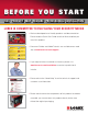
BEFORE YOU START THIS PRODUCT MAY REQUIRE PROFESSIONAL INSTALLATION LOREX IS COMMITTED TO FULFILLING YOUR SECURITY NEEDS • We have developed user friendly products and documentation. Please read the Quick Start Guide and User Manual before you install this product. • Consumer Guides and Video Tutorials are available on our web site at www.lorexcctv.com/support • If you require further installation assistance, please visit www.lorexcctv.com/installation or contact a professional installer.
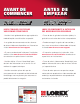
AVANT DE COMMENCER ANTES DE EMPEZAR CE PRODUIT POURRAIT EXIGER UNE INSTALLATION PROFESSIONNELLE ESTE PRODUCTO PUEDE EXIGIR UNA INSTALACIÓN PROFESIONAL LOREX S’ENGAGE À SATISFAIRE VOS BESOINS SÉCURITAIRES LOREX SE COMPROMETE A SATISFACER SUS NECESIDADES EN SEGURIDAD • Veuillez lire le guide de démarrage rapide et le mode d’emploi avant d’installer ce produit. • Favor de leer la guía de instalación rápida y la guía del usuario antes de instalar este producto.
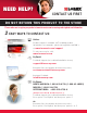
NEED HELP? CONTACT US FIRST DO NOT RETURN THIS PRODUCT TO THE STORE Please make sure to register your product at www.lorexcctv.com to receive product updates and information 3 Easy Ways to Contact Us: Online: Product Support is available 24/7 including product information, user manuals, quick start up guides an d F A Q ’ s at www.lorexcctv.com/support To order accessories, visit w ww.lorexcctv.com By Email: Technical Support (for technical/installation issues) s u pport@lorexcorp.
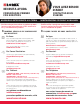
NECESITA AYUDA VOUS AVEZ BESOIN D’AIDE? COMUNÍQUESE PRIMERO CON NOSOTROS CONTACTEZ-NOUS D’ABORD NO DEVUELVA ESTE PRODUCTO A LA TIENDA NE RETOURNEZ PAS CE PRODUIT AU MAGASIN Cerciórese de por favor colocar su producto en www. lorexcctv.com/registration para recibir actualizaciones y la información del producto Veuillez veiller à enregistrer votre produit à www. lorexcctv.
Important Safeguards Important Safeguards In addition to the careful attention devoted to quality standards in the manufacture process of your video product, safety is a major factor in the design of every instrument. However, safety is your responsibility too. This sheet lists important information that will help to assure your enjoyment and proper use of the video product and accessory equipment. Please read them carefully before operating and using your video product. Installation 1. 2. 3. 4.
Important Safeguards Service Use 13. Servicing - Do not attempt to service this video equipment yourself as opening or removing covers may expose you to dangerous voltage or other hazards. Refer all servicing to qualified service personnel. 19. Cleaning - Unplug the video product from the wall outlet before cleaning. Do not use liquid cleaners or aerosol cleaners. Use a damp cloth for cleaning. 14.
General Precautions General Precautions 1. All warnings and instructions in this manual should be followed 2. Remove the plug from the outlet before cleaning. Do not use liquid aerosol detergents. Use a water dampened cloth for cleaning 3. Do not use this unit in humid or wet places 4. Keep enough space around the unit for ventilation.
Features Features • • • • • • Latest Ultra Digital Wireless Technology provides excellent image quality and clarity Connect up to 4 receivers to your surveillance recorder (DVR) to create a wireless surveillance solution† Infrared night vision LED's allow you to see in total darkness Up to 150ft (46m) indoor / 450ft (137m) outdoor wireless range* View one particular channel, cycle through all channels or view all 4 channels on one screen (Quad view)** Auto infrared light filter ensures outstanding image q
Table of Contents Table of Contents Getting Started ................................................................................................................................................ 8 Wireless Receiver ........................................................................................................................................... 9 Connecting the Camera...................................................................................................................................
Getting Started Getting Started The System comes with the following components: 1 x WIRELESS CAMERA* 1 x CAMERA MOUNTING STAND 1 x MOUNTING SCREW KIT 1 X WIRELESS ANTENNA (FOR RECEIVER) 2 x POWER ADAPTERS (FOR RECEIVER & CAMERA) 1 x WIRELESS RECEIVER 1 x BNC/RCA ADAPTER 3ft/1m BNC Female/BNC Male Extension Cable *Camera configuration may vary by model CHECK YOUR PACKAGE TO CONFIRM THAT YOU HAVE RECEIVED THE COMPLETE SYSTEM, INCLUDING ALL COMPONENTS SHOWN ABOVE.
Wireless Receiver Wireless Receiver 1. Wireless Antenna: Screws onto to the top of the receiver. 2. Channel LEDs: When lit up, indicates the current viewing mode. 3. Resolution* button: Press to switch between VGA and QVGA video resolutions; press and hold for several seconds to remove/replace channels from Auto-Scan. See page 14 for more details. 4. Front LED: Lit in green to indicate power to the receiver. 5.
Connecting the Camera Installation Warnings: • • • Aim the Cameras to best optimize the viewing area: Select a location for the camera that provides a clear view of the area you want to monitor, which is free from dust, and is not in line-of-sight to a strong light source or direct sunlight. Avoid installing the cameras where there are thick walls or obstructions between the Cameras and the Receiver*.
Setting up the Wireless Receiver Setting up the Wireless Receiver To connect the wireless receiver to a surveillance recorder (DVR): 1. Screw the antenna onto the top of the receiver. 2. Connect the BNC connector on the receiver directly into an available video input. NOTE: If necessary, attach the 3ft (1m) BNC/BNC extension cable at one end to the receiver and at the other end to the surveillance recorder. 3.
Viewing Modes Viewing Modes There are six different viewing modes available on the system: individual viewing of channels 1~4, Quad split-screen, and Auto-Scan. For details on Auto-Scan, see page 14. Press the CHANNEL button repeatedly to switch between these viewing modes. AUTO Auto-Scan mode Quad mode Channel 1 RESOLUTION CHANNEL Press the CHANNEL button to change viewing modes* Channel 4 Channel 2 Channel 3 Figure 3.0 View Mode diagram *Images simulated.
On-Screen Display On-Screen Display 1 2 1. Signal Indicator – The signal indicator shows the strength of the signal being received from the camera. The number of bars in the Signal Indicator shows the strength of the signal – One or No Bars indicates the signal is poor, and 4 bars indicate a very strong signal. NOTE: Signal Indicator not shown while in Quad Mode. ATTENTION: If signal is low (e.g. 1 or 2 bars) adjust the antennas, or reposition the cameras or receiver for best performance. Figure 4.
Adding Cameras Adding Cameras The System comes with a camera that has already been paired. The Pairing Function assigns each camera to a different channel on the Wireless Receiver (up to four cameras), and is necessary for configuring additional cameras. By default, the camera included with the system appears on channels 1 on the wireless receiver. NOTE: It is highly recommended to pair the cameras to the receiver before permanently mounting the cameras. 1.
Setting Dwell Time Setting Dwell Time You can set the length of time (in seconds) that the receiver displays each channel while in Auto Scan. To set dwell time: 1. Make sure the Wireless Receiver and cameras are fully connected and powered on. 2. Press and hold the RESOLUTION button and CHANNEL button at the same until the Dwell Time screen appears. Continue holding both buttons. 3.
Appendix A: System Specifications Appendix A: System Specifications Receiver Specifications Receiver Receiving Frequency Range RX Sensitivity Demodulation Data Rate Supported Resolutions Power Requirement Power Consumption Operating Temp Range 2.400GHz~2.
Appendix B: About Digital Wireless Technology Appendix B: About Digital Wireless Technology The Digital Wireless signal transmission type used by the Lorex LW2100 is also known as FHSS –Frequency Hopping Spread Spectrum. This type of signal is highly resistant to deliberate jamming as it generates a channel hopping sequence using an algorithm generated by the receiver system. The 2.4GHz (2.400-2.
Appendix C: Strengthening the Range of the Wireless Signal Appendix C: Strengthening the Range of the Wireless Signal Is your wireless signal choppy? Do you want to extend the range of wireless transmission? There are several ways to boost your wireless signal as well as options to help you extend the range of the wireless signal. Clear Line-of-Sight The digital wireless signal is virtually interference free.
Appendix C: Strengthening the Range of the Wireless Signal 2.4 GHZ Directional Panel Antenna Use the 2.4GHz Directional Panel Antenna (model#: ACCANTD9) in one of two scenarios: SCENARIO 1—Single camera installation: Attach the directional antenna to either the camera or receiver or both to extend the range. SCENARIO 2—Multi-camera installation: Attach the directional antenna to those cameras which are located far away to improve the wireless signal strength. A 20 ft.
Appendix C: Strengthening the Range of the Wireless Signal 2.4 GHZ Omni-Directional Antenna Use the 2.4GHz Omni-Directional Antenna (model#: ACCANTO8) in the following scenario: Multi-camera installation: Attach the Omni-Directional antenna to the receiver to extend the wireless transmission range of the receiver. To further improve the strength of the wireless signal, consider adding directional antennas to those cameras which are located far away.
Troubleshooting Troubleshooting If you have problems with your System, there is often a quick and simple solution. Please try the following: Problem There is no picture from a camera. There is interference with the camera picture. The picture is dropping The picture is or has become choppy The picture appears to be grainy/distorted The picture is white Solution • Check power to the Camera.
FAQ FAQ Q: What is the maximum distance I can have between the camera and the receiver? A: Typically 450 feet (137 m) with a clear line of sight in open space, or approximately 150 feet (46 m) in a house. Walls, studs, furniture will interfere with the range of wireless transmission. Q: Why does my “wireless camera” have a power cable? A: The term “wireless” refers to the lack of a video cable between the camera and the receiver. The camera still requires a power source.
Revision 3.
Soyez toujours très discret lorsque vous installez des systèmes de surveillance, surtout dans les endroits plus retirés. Informezvous au sujet des lois et règlements municipaux, provinciaux ou fédéraux qui s’appliquent à l’installation d’appareils de surveillance audio et vidéo. Il se peut que le consentement de la partie surveillée soit exigé.
See Hear PROTECT Enhance your security with genuine Lorex Cameras, Digital Video Recorders, Integrated Systems and Accessories. Order whatever you need at www.lorexcctv.