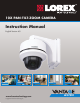
0X PAN-TILT-ZOOM CAMERA Instruction Manual English Version 4.0 RETAIL INDUSTRY www.lorextechnology.com Copyright © 2013 Lorex Technology Inc.
Thank you for purchasing the LOREX Super+ Resolution 10X PTZ Speed-Dome Camera. This manual refers to the following models: • LZC7091 For the latest online manual and to learn about our complete range of accessory products, please visit our website at: www.lorextechnology.com CAUTION RISK OF ELECTRIC SHOCK DO NOT OPEN DURING OPERATION CAUTION: NO USER SERVICABLE PARTS INSIDE. REFER SERVICING TO QUALIFIED SERVICE PERSONNEL.
NEED HELP? CO NTACT US F I R S T DO NOT RETURN THIS PRODUCT TO THE STORE Please make sure to register your product at www.lorextechnology.com to receive product updates and technical support. 2 Easy Ways to Contact Us Online: Product Support is available 24/7 including product information, user manuals, quick start up guides and FAQ’s at www.lorextechnology.com/support For all other matters, visit www.lorextechnology.
VIEW YOUR WORLD™ VOIR VOTRE MONDEMD VEA SU MUNDO™ ¿NECESITA AYUDA? BESOIN D’ASSISTANCE? COMUNÍQUESE PRIMERO CON NOSOTROS COMMUNIQUEZ D’ABORD AVEC NOUS NO DEVUELVA ESTE PRODUCTO A LA TIENDA NE RETOURNEZ PAS CE PRODUIT AU MAGASIN Por favor, registre su producto en www.lorextechnology. com para recibir actualizaciones del producto y asistencia técnica. Veuillez enregistrer votre produit sur le site www.lorextechnology.com afin de recevoir des mises à jour et le soutien technique pour votre produit.
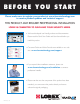
B E F O R E Y O U S TA R T Please make sure to register your product at www.lorextechnology.com to receive product updates and technical support THIS PRODUCT MAY REQUIRE PROFESSIONAL INSTALLATION LOREX IS COMMITTED TO FULFILLING YOUR SECURITY NEEDS • We have developed user friendly products and documentation. Please read the Quick Start Guide and User Manual before you install this product. • Consumer Guides and Video Tutorials are available on our web site at www.lorextechnology.
AVANT DE COMMENCER ANTES DE EMPEZAR Veuillez enregistrer votre produit sur le site www.lorextechnology.com afin de recevoir des mises à jour et le soutien technique pour votre produit. Cerciórese de por favor colocar su producto en www.lorextechnology.com para recibir actualizaciones y la información del producto y soporte técnico.
Features English • Latest Sony EXview™ II image sensor for best-in-class low light performance1 • Sony Effio™ video image processor delivers up to 700TV lines of resolution • 10X Optical Zoom and 10X Digital Zoom to focus in on even the finest details • Complete area coverage with 360 degrees per second panning speed • Program preset viewing points when connected to a DVR • ClearNight technology with Digital Noise Reduction improves low light performance and recording efficiency by up to 30% • Accurate col
Safety Instructions • Read this guide carefully and keep it for future reference. • Follow all instructions for safe use of the product and handle with care. • Use the camera within given temperature, humidity, and voltage levels noted in the Technical Specifications. • Camera is rated for outdoor use and is weatherproof using included wall mount only. For indoor installations, camera may be directly attached to a ceiling. • Camera is not intended for submersion in water.
TABLE OF CONTENTS English 1. Getting Started . . . . . . . . . . . . . . . . . . . . . . . . . . . . . . . . . 1 2. Connecting the Camera . . . . . . . . . . . . . . . . . . . . . . . . . . 2 2.1 Default Protocol Information . . . . . . . . . . . . . . . . . . . . . . . . . . . .6 3. Installation. . . . . . . . . . . . . . . . . . . . . . . . . . . . . . . . . . . . . 7 3.1 Installation Tips and Warnings . . . . . . . . . . . . . . . . . . . . . . . . . . .7 3.2 Extension Cables . . . . . . . . . . . . .
iv
Getting Started 1.
Connecting the Camera 2. CONNECTING THE CAMERA It is recommended to connect the camera to your DVR and test the PTZ controls before permanent installation.
1. Connect the 6-pin connector on the 3ft cable to the camera. • To do this, you must remove the camera from the case. Rotate the dome cover counterclockwise to remove. Remove the base attachment screws (3x) and remove the camera base. See illustration below. Base attachment Dome screws cover Camera Camera base Removing the camera from the case NOTE: Do not use force when pulling out the 6-pin connector. The 6-pin connector has a release latch under the connector.
Connecting the Camera 3. Use a Philips screwdriver (not included) to loosen the 2 screws on the RS485 connection block furthest from the pre-attached wires. Insert the RS485 wires into the RS485 connection block (red to red, black to black). Tighten the screws on the RS485 connection block to Loosen screws Insert wires secure the wires in place. 4. Connect the BNC female connector on the 3ft cable to the BNC male connector on the 100ft extension cable. 5.
Connecting the Camera English • If the wires can be easily removed, they may become disconnected and affect control of the camera. Use wire strippers (not included) to expose more of the wires if needed. 7. Connect the male BNC connector on the 100ft extension cable to an available Video IN port on the DVR.
Connecting the Camera 2.1 DEFAULT PROTOCOL INFORMATION Unlike standard security cameras, PTZ (pan-tilt-zoom) cameras require special protocol information to enable a Security DVR to control the camera movement. Input the following information into your DVR to enable PTZ controls. • Default ID: 1 • Default Baud Rate: 2400 • Default Protocol: Pelco-D For details on setting up your DVR with the PTZ camera, see “Controlling the PTZ Camera with your DVR” on page 16.
Installation 3. INSTALLATION English 3.1 INSTALLATION TIPS AND WARNINGS Make sure to install the camera in a location that can support the camera weight. Make sure there are no live electrical cables in the area where you plan to mount the camera. • Camera is rated for outdoor use and is weatherproof using included wall mount only. For indoor installations, camera may be directly attached to a ceiling.
Installation 3.2 EXTENSION CABLES • Included extension cable is 100ft / 30m long. • Because this is a high-powered PTZ camera, the power cable cannot be extended beyond 100ft. • Alternatively, you may connect the included power adapter directly to the camera’s power connector and plug the adapter into a power outlet near the camera. Use the included 100ft extension cable to connect RS485 and BNC cables to your DVR or use the guidelines below to extend the RS485 signal.
Installation 3.3 WALL MOUNT INSTALLATION (INDOOR/ OUTDOOR) English Make sure to disconnect the power adapter before installing the camera. Camera will begin moving immediately when power adapter is connected. Camera can be installed to a wall using the included wall mount. This method is suitable for indoor or outdoor installations. To install the camera: 1. Make sure the O-rings (3x) are attached to the top of the pendant cap (spares are included).
Installation 3. Rotate the camera dome cover counterclockwise to remove. 3 Dome cover 4. Remove the base attachment screws (3x) and remove the camera from the camera base. 4 Base attachment screws Camera Camera base 5. Remove the rubber plug on the bottom of the camera base and run the single end of the cable through the bottom of the camera base. Attach the camera base to the pendant cap using the camera attachment screws (4x).
Installation 7. Remove the protective vinyl sheet from the dome cover. • For details on DVR setup, see “Controlling the PTZ Camera with your DVR” on page 16. 6 English 6. Connect the cable to the camera (see “Connecting the Camera” on page 2). Attach the camera to the base using the base attachment screws (3x) then reattach the dome cover by rotating it clockwise. NOTE: Make sure power adapter is disconnected before connecting the 6-pin connector.
Installation 3.4 CEILING INSTALL (INDOOR ONLY) Make sure to disconnect the power adapter before installing the camera. Camera will begin moving immediately when power adapter is connected. Camera is not weatherproof if installed using this method. Use the included wall mount for outdoor installations. Camera can be installed directly to a ceiling. To install the camera: 1 1.
Installation 3. Remove the base attachment screws (3x) and remove the camera from the camera base. 3 Base attachment screws English Camera Camera base 4. Remove the rubber plug on the bottom of the camera base and run the 6-pin connector through the cable hole. 5. Drill holes for the mounting screws (x4) and the cable and run the cable through the hole.
Installation 6. Attach the camera base to the ceiling using the included mounting screws (x4). NOTE: Use the included drywall anchors if installing the camera in drywall. 6 Mounting screws 7. Connect the 6-pin connector to the camera. NOTE: Make sure power adapter is disconnected before connecting the 6-pin connector. Camera will begin moving immediately when power adapter is connected. 8. Attach the camera to the base using the base attachment screws (3x).
Installation 9. Reattach the dome cover by rotating it clockwise. Remove protective vinyl from dome cover. 9 English 10.Connect the cables. For details, see “Connecting the Camera” on page 2. • For details on DVR setup, see “Controlling the PTZ Camera with your DVR” on page 16.
Controlling the PTZ Camera with your DVR 4. CONTROLLING THE PTZ CAMERA WITH YOUR DVR Once your camera is connected to the DVR, you must perform initial setup to control the camera using the DVR. Once this setup is complete, you will be able to move the camera, configure preset positions, and use other advanced controls. PTZ features that are available to you will depend on the model of DVR that you have. The following instructions are based on the Lorex ECO2 DVR’s (LH130 Series).
Controlling the PTZ Camera with your DVR English 4. Configure the following: • Channel: Select the channel the camera is connected to. • Protocol: Select the protocol (default: Pelco-D). • Baud rate: Select the camera’s baud rate (default: 2400). • Data Bit: Select 8. • Stop Bit: Select 1. • Parity: Select None. • Cruise: Select Enable to enable PTZ cruise. • Address: Enter the camera’s ID (default: 001). 5. Click Apply to save your settings. 4.
Controlling the PTZ Camera with your DVR 3. Use the on-screen PTZ controls to control the camera. Speed Slider: Channel: Increase or decrease the pan and tilt speed Select the channel with the PTZ camera Direction keys: Click to pan and tilt the camera Click + / - to adjust the camera Zoom, Focus, and Iris settings Camera Pre-set controls (see page 19) ATTENTION: This PTZ camera is designed tilt up and down within a range of 155°.
Controlling the PTZ Camera with your DVR 4.3 PTZ PRESETS AND PTZ CRUISE A PTZ cruise (referred to on some DVR’s as a tour or scan), allows you to configure a sequence of presets that the camera will automatically cycle through. This is useful if you want the camera to monitor a large area, without manually having to control the camera. NOTE: These features may not be available on all DVR’s. Check your DVR instruction manual for details. 4.4 SETTING PTZ PRESETS ON THE ECO2 DVR 1.
Controlling the PTZ Camera with your DVR 4. Complete the steps above to create additional presets as needed. Press Save when you are finished to save all created presets. 4.5 SELECTING PTZ PRESETS ON THE ECO2 DVR 1. In the No. field, select the number of the preset you would like to select. 2. Click Go to to go to the preset. 4.6 DELETING PTZ PRESETS ON THE ECO2 DVR 1. In the No. field, select the number of the preset you would like to delete. 2.
Changing Protocol Information The camera’s PTZ protocol information allows a DVR to communicate with it and control the camera’s movement. You will not need to change the default protocol information on your camera unless you are using multiple PTZ cameras or if your DVR does not support the default settings (see your DVR’s instruction manual for details). PTZ protocol information on this camera is set using DIP switches on the bottom of the camera. DIP switches represent binary values.
Changing Protocol Information 5.1 ACCESSING THE DIP SWITCHES To access the DIP switches, you must remove the camera from the case. To do this, you must remove the camera from the case. Rotate the dome cover counterclockwise to remove. Remove the base attachment screws (3x) and remove the camera base. See illustration below. Dome cover Base attachment screws Camera Camera base Removing the camera from the case 5.2 SETTING THE CAMERA ID The camera ID is how the DVR identifies PTZ cameras.
Changing Protocol Information You cannot use the same ID for more than 1 PTZ camera. IMPORTANT ID English You cannot set an ID with a value of 0.
Changing Protocol Information 5.3 SETTING THE CAMERA PROTOCOL AND BAUD RATE The protocol is the language that allows the camera and DVR to communicate, and the baud rate is the frequency of signal sent to the camera. The camera supports Pelco-D and Pelco-P protocols. Protocol and baud rate are set using switches 1&2 on the smaller DIP switch panel. See the table below.
Technical Specifications Image Sensor 1/3" Sony Ex-View HAD CCD II Video Format NTSC Effective Pixels 976(H) x 494 (V) Resolution up to 700 TVL Range 360° Pan (Endless) 155° Tilt (Auto-Flip) Pan/Tilt Speed Max 360°/Sec. Zoom 10x Optical Zoom & 10x Digital Zoom Protocol Pelco-D, Pelco-P Min. Illumination 0.7 Lux in Color 0.02 Lux in Black and White Lens / Lens Type Auto Focus / 3.8-38mm F 1.
Dimensions 7.
Troubleshooting 8. TROUBLESHOOTING • Camera is capable of seeing in extremely low light conditions (0.02 Lux), but it cannot see in total darkness. It is recommended to install the camera where there is some ambient light (e.g. street lighting or starlight, moonlight, etc.) or leave a light on in the area where the camera is installed. No image at startup • Check to ensure your camera is properly connected (see “Connecting the Camera” on page 2) and the power adapter is plugged in.
Troubleshooting PTZ controls are not working or are not working properly • RS485 wires not connected or connected using wrong polarity. Ensure the red wire is connected to the + RS485 port and the black wire is connected to the - RS485 port. • Not enough of RS485 wire is exposed to make proper connection. Use a wire stripper (not included) to strip off some of the wire insulation. • Extension cables may be damaged or are not connected properly. Check your extension cable run.
EXPAND AND CUSTOMIZE YOUR SYSTEM WITH A FULL RANGE OF CAMERAS & ACCESSORIES Specialty Cameras Wireless Cameras Dome Cameras Digital Video Recorders Monitors Simulated Cameras Security Hard Disc Drives Extension Cables Accessories www.lorextechnology.