Xcelorin Brushless Electronic Speed Control Thank you for purchasing the Losi™ Xcelorin™ Electronic Speed Control (ESC). This ESC will provide you the benefit of the latest in brushless technology. Featuring an advanced software interface with which you can finely tune the feel of the ESC to your needs, or use the 8th Quick Programming Card (8QPC) to make adjustments. We believe it will be to your benefit to take the time and effort to read this manual.
Table of Contents Overview ........................................................................................... 3 Profile Overview ................................................................................. 5 Initial Profile Setting from the Factory ................................................... 6 Overriding the Active Profile ................................................................. 7 Selecting Profiles ..............................................................................
Overview The Losi Xcelorin electronic speed control (ESC) is specifically designed for operating sensorless brushless motors. Featuring low on-resistance, enhanced throttle response and strong brakes, this ESC has enough features to satisfy the most demanding driver. The pre-installed high airflow fan attached to the ESC heat sinks keep it cool and performing to the peak of its ability.
A key feature is the three (3) stored settings within the ESC that are easily recalled for convenient use. These stored settings are referred to as “profiles.” There are also two (2) user profiles that are written to by using the supplied software. These do not limit the functions of the ESC as you can easily use the included 8th Quick Programming Card (8QPC) to make changes to any desired setting. The Low Voltage Cutoff (LVC) is preset for 4S LiPo batteries.
Profile Overview These stored settings, also referred to as “profiles,” are defined as follows: Profile #1 - “3S LiPo battery” Cutoff Voltage - LiPo 3S BEC – 6.0V Brake/Reverse Role- Forward only ** Motor Timing- Low Initial Acceleration- High Drag Brake - 4% ** Brake - 20% ** Throttle Limit – 0% (No limit) Reverse Throttle Limit – Not active Profile #2 - (Default) “4S LiPo battery” Cutoff Voltage - LiPo 4S BEC – 6.
Profile #3 - “5S LiPo battery” Cutoff Voltage - LiPo 5S BEC – 6.0V Brake/Reverse Role - Forward only ** Motor Timing - Low Initial Acceleration - High Drag Brake - 4% ** Brake - 20% ** Throttle Limit – 0% (No limit) Reverse Throttle Limit – Not active ** 8QPC can change these settings NOTE: You must use the supplied Xcelorin Setup Software to access all features of the ESC.
Initial Acceleration Drag Brake Brake Legacy or 2.4GHz Reverse Throttle Limit Neutral Deadband Reverse Rotation Throttle Profile Brake Profile High 4% 20% 2.4GHz Not active 3 Blank Linear Linear Overriding the Active Profile There are three (3) saved, and two (2) user profiles within the ESC that were previously described. To override a setting within the active profile, select a saved profile that resembles your needs, or make further changes to the current profile.
For example if you have the ESC active profile set to Profile #2 (Default) and would like a little more brake but would like nothing else changed, place the jumpers on the following choices. Brake - 30% (default is 20%) Drag Brake – 4% Brake/Reverse Role- Forward only Radio System - 2.4GHz Then follow the instructions for using the Quick Programming Card. You can change one setting at a time or any combination. Making the above change is ONLY overriding the active profile.
4. Release setup button. 5. The status LEDs flash to indicate the current profile setting. LED status for each Profile below: Profile 1 Yellow and Blue LEDs flash Profile 2 Yellow, Blue and Green LEDs flash (default setting) Profile 3 Yellow, Blue, Green and Red LEDs Flash Profile 4 Red and Blue LEDs flash Profile 5 Yellow and Green LEDs flashing quickly 6. To make a change, quickly press the setup button, which will advance you to the next profile.9 7.
8. If you do not press the setup button within 15 seconds, the four status LEDs will scroll to indicate you are exiting programming. The ESC will return to neutral and be ready for use without any change. Modifying the ACTIVE Profile The Xcelorin 8th Quick Programming Card (8QPC) is used to make all adjustments to the active profile in your ESC. Any ACTIVE profile can be modified. LOSB9516 Xcelorin Electronic Speed Control v1.
Using the Advanced 8QPC, you can set the following: Brake/Reverse Operating Mode • Forward w/o Reverse • Forward pause then Reverse • Legacy Radio System • 2.4GHz Radio System Braking Strength Drag Brake • 10% • 20% • 30% • • • • LOSB9516 Xcelorin Electronic Speed Control v1.
Using the Quick Programming Card With the 8QPC in your hand and the back facing you, notice the small jumper connectors. The jumpers are used to indicate which function you want to activate. To change the settings rearrange the small jumpers to the desired settings. To upload to the ESC do the following: 1. Ensure the transmitter and vehicle are turned off. 2. Make sure a battery pack is installed that has some charge in it. 3. Connect the battery to the ESC. 4.
6. Connect the Signal wire to the top of the 8QPC, ensure it is connected correctly. 7. Pay close attention to the ESC LEDs and you will notice the Red LED flash, and on the 8QPC the Red LED will come on. If you do not notice the ESC Red LED flash, you can unplug the Signal wire from the 8QPC and reconnect again to verify the operation of the Red LEDs. Once you see the ESC Red flash and the 8QPC turn on Red, the ESC has accepted the programming. 8.
Setup/Calibration to Transmitter To perform the setup/calibration between the ESC and Transmitter follow these steps: 1. Turn on the transmitter. 2. While turning on the vehicle Press and Hold the setup button, notice the Yellow LED is now ON solid. When the Yellow LED is on solid, you can release the setup button. Note: If you cannot get the ESC to Calibrate, you may need to reverse your Throttle Servo on the transmitter. 3. Using the throttle trigger pull Full Throttle until the Green LED is ON solid. 4.
6. Turn off the vehicle/ESC power switch. 7. Turn the vehicle/ESC back ON; you are now ready to use the ESC. Normal Operation • After turning on the vehicle, the Blue LED will be on for normal operation. • If reverse is active then you will notice the Yellow LED is also on. Confirmation of Full Throttle and Brake • While the ESC is on and operational, if you pull the throttle trigger to Full Throttle the Green LED will turn ON solid.
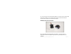
Connect the Xcelorin ESC and Sensorless Motor There are three wires from the ESC a black, blue and white for the motor. Each wire will be soldered to a single motor tab. Make certain there is not a short across any of the motor connections. If shorted together, you will damage the ESC when the batteries are connected. If the motor you are using runs backwards after installation, you can correct this in one of two ways: • Switch any two motor wires on the ESC.
Connecting the Xcelorin ESC to your Receiver The Receiver wire will connect to nearly all current receivers. Plug it into the Throttle Channel of the receiver. Brown Negative Red Positive Orange Signal LOSB9516 Xcelorin Electronic Speed Control v1.
Xcelorin Software Installation In the box along with your Electronic Speed Control, you will find: • • • Xcelorin Software CD USB Cable USB Adapter Requirements: • • • • Windows Operating System preferably Windows XP or higher USB Port to be available compatible with USB 1.
1. Now, insert the CD into your CD/DVD Player. The following should automatically display. LOSB9516 Xcelorin Electronic Speed Control v1.
2. When ready select the Next button. If you wish to cancel, select the Exit button. If you do not get the previous panel, click on My Computer and then select (click on) the CD/DVD Drive to open it. You should then have a panel similar to the one below. Select and click on the Losi Setup.exe program icon. (You will now see the panel expected in step 1 above.) LOSB9516 Xcelorin Electronic Speed Control v1.
3. The following should now be presented. You can change the default directory if desired, we recommend using this default. When ready select the Next button. If you wish to cancel, select the Exit button. LOSB9516 Xcelorin Electronic Speed Control v1.
4. The following should now be displayed and confirms the install location. When ready, select the Start button. If you wish to cancel, select the Exit button. LOSB9516 Xcelorin Electronic Speed Control v1.
5. The following panel should now be presented, and confirms install was successful. Select the Exit button to finish. LOSB9516 Xcelorin Electronic Speed Control v1.
6. Connect the USB cable to your Windows PC or Laptop computer. 7. Connect the Xcelorin USB Adapter to the mini USB connector on the USB Cable. You will be prompted to install the device drivers. They are both unsigned so select OK and continue. After a few moments, the USB adapter LED will turn from Red to Green. If your Adapter LED remains Red, then disconnect the Adapter, wait a minute and then reconnect. If the Green LED does not come on, please reboot before calling Horizon support at 1 877-504-0233.
Notice in the Connection box the USB is Green and the ESC is still Red. 9. You are ready to connect the Adapter to the ESC, using the Signal Wire. WARNING: Disconnect the battery from the ESC before connecting the Xcelorin USB adapter to the speed control. Failure to do so may result in DAMAGE TO YOUR COMPUTER LOSB9516 Xcelorin Electronic Speed Control v1.
Please note the label on the USB adapter; there are 3 color bars each marked which indicate how to connect the signal wire to the adapter. 10. With the ESC connected to the USB Adapter, the Xcelorin Software Connection status icons should now both be GREEN. The Losi Xcelorin software is now installed and ready for use. LOSB9516 Xcelorin Electronic Speed Control v1.
Xcelorin Software Overview Using this you will find it quite easy to configure your new speed control. On the main panel, you will notice this button , if you click on this the specific help for that function will display. Take a moment to review the selectable functions, and read the specific help text for each to become familiar with them. To make configuration changes to a function select the setting you want, and from the drop down menu select your new choice or option.
General Tab: Here you will find the following configuration settings: Battery Type and Cutoff Voltage, Brake/Reverse, Motor Timing, Initial Acceleration, Percent Drag Brake, ESC operating mode, Deadband adjustment, Braking Percentage, Throttle Limit, Reverse Throttle Limit and Motor Rotation. All changes are done at your own risk. Throttle Tab: Only recommended for more experienced Electronic Speed Control users. You can remap the throttle profile from the default linear line.
Upgrade Firmware: Use of this button will begin the firmware upgrade process. The following pop up will be displayed, and you need to select the location of the firmware update file. You may cancel this process here without any effect to the ESC firmware. After finding and selecting the file, this confirmation screen will then display. You may still cancel at this time without any effect to the ESC firmware. LOSB9516 Xcelorin Electronic Speed Control v1.
If you select OK, the progress status percentage of the upgrade will be displayed in the lower right. Please do not unplug your computer or the ESC while the upgrade is in progress or damage to the ESC may result. If no problems were encountered, OK will be displayed and the configuration redisplayed. You are finished with the upgrade and you can re-configure the ESC or end the program. If a problem is encountered and the upgrade fails, simply restart the upgrade process again.
DO NOT load previous versions of firmware without contacting support first or you may damage your ESC. Current Software: grayed out, shows the software currently on the controller. Xcelorin ESC Model is indicated by the first character in the Software Level. C0101XX.LSC - 18th Xcelorin D0101XX.LSC - 10th Xcelorin Sensored E0101XX.LSC - 10th Xcelorin Sensorless F0101XX.LSC - 8th Xcelorin Sensorless G0101XX.
General TAB Information Battery Type –Select NiMH, or Lithium-Ion/Lithium Polymer batteries Cutoff Voltage – This is a critical option to understand and used to protect Lithium or M1 batteries from being over-discharged, which will shorten the life, cause damage to the battery, or even result in Fire or Personal Injury. When using NiMH batteries you do not need to set a cutoff voltage to protect the batteries. NiMH batteries typically stop operating your vehicle before any damage occurs.
When using any Lithium or M1 (A123) batteries, they must not be discharged to less than 3.0V per cell. • No Cutoff The choice is not available and NOT recommended when using any type of Lithium battery. • Customize Voltage Cutoff (for Lithium Batteries) after selecting the number of cells (2 thru 5) the default voltage is displayed. For example, you select a 2S battery; the default cutoff voltage will be 6.0V (# of cells multiply by 3.0V). You may raise this to protect your expensive batteries in 0.
Throttle Limit – Use this to limit the power available using forward throttle. The lower the percent the less forward throttle speed will be available.
Motor Timing - This option affects the power band and efficiency (run time) of an electric motor. The default is “Normal” and is a good starting point to deliver power and provide good run time. • Very Low Provides power for running through soft surfaces, having fun and longer run time. • Low (Default) Provides maximum efficiency with less power. Higher timing produces significantly more power but at the expense of efficiency (less run time) and typically the motor will generate more heat.
Initial Acceleration - Use this to limit the initial power that is sent to the motor when starting from a complete stop. Using the LOW option, the vehicle will launch very slowly and provide the longest run times. When using the HIGH choice, you will have wheel-spinning acceleration at the cost of run time. This is also very tough on the batteries as the amperage draw can be very high. • • • Low Using this option will provide longer run times and is easiest on the batteries.
Braking Percent - Gives you the ability to have full control over the amount of brake your vehicle will have. NOTE: Selecting the advanced function “BRAKE CURVE” and using this method to adjust the feel of the desired brake strength will override the “Braking Percent” parameter. • 10% Effect will be 10% of full brakes • 20% Effect will be 20% of full brakes. • 30% Effect will be 30% of full brakes • 40% Effect will be 40% of full brakes.
• 0% • 15% • 4% (Default) • 20% • 8% • 25% • 30% • 10% • 12% Note: Higher motor temperatures occur with each increase in Drag Brakes. Battery Elimination Circuit (BEC) – Can be adjusted to provide any of the following voltages thru the receiver to the radio system. Generally 6.0V is used to power the receiver and servo. • 5.2V • 5.6V • 6.0V • 6.5V Legacy or 2.4GHz – This setting is intended to reflect what type of Radio System you are using, i.e. Transmitter and Receiver. Default is 2.
Neutral Deadband – This setting adjusts the amount of Deadband off neutral on the throttle trigger. This is in milliseconds (MS) and is the amount of neutral when you pull the trigger. The smaller the value the less Deadband or movement is required off-center for the ESC to begin throttle functions. Using a higher value for this setting will provide a wider Deadband.
Throttle TAB information Setting Throttle Profile – You can select either Linear (Default) or Curve. Using Curve will activate changes you may have made to the left for the throttle profile. Using the Left Mouse Button, you may click to select a point on the throttle line and drag it into the desired position. Generally, movement to the upper left will cause accelerated throttle action, and movement to the lower right will slow (or delay) the throttle action. LOSB9516 Xcelorin Electronic Speed Control v1.
Below is an example of a slow ramp up to full throttle versus the above linear graph. LOSB9516 Xcelorin Electronic Speed Control v1.
Below is an example of an accelerated ramp up to full throttle. LOSB9516 Xcelorin Electronic Speed Control v1.
Brake TAB Information Setting Brake Profile – You can select either Linear (Default) or Curve. Using Curve will activate changes you may have made to the left for the throttle profile. Using the Left Mouse Button, you may click to select a point on the throttle line and drag it into the desired position. Generally, movement to the upper left will cause accelerated braking action, and movement to the lower right will slow (or delay) the braking action. LOSB9516 Xcelorin Electronic Speed Control v1.
Below is an example of a gradual increase in braking versus the above linear graph. LOSB9516 Xcelorin Electronic Speed Control v1.
Below is an example of increase of braking action then leveling to full brake. LOSB9516 Xcelorin Electronic Speed Control v1.
Xcelorin Sensorless Brushless ESC Specifications Type: Sensorless Brushless ONLY Cells w/BEC: 6-12 Cells (NiMH)/ 2S-5S (LiPo) Auto Cutoff: Programmable BEC Voltage: Programmable from 5.2V up to 6.5V at 6A Forward: Y Reverse: Y Brake: Y Continuous Maximum Current: 160A Momentary Peak Current: 800A Input Connector Types: Losi EC5 style Motor Limit: Losi 8th scale 720 sensorless motors of 3000Kv or less Dimensions (WxLxH): 2.40x2.56x1.80 in (61x65x46mm) Weight: 5.
Xcelorin Replacement Parts LOSB9353 LOSB9358 LOSB9359 LOSB9363 LOSB9364 LOSB9368 LOSB9381 LOSB9382 LOSB9383 LOSB9384 LOSB9385 LOSB9620 LOSB9621 LOSB9622 Heat Sink: 1/8 Xcelorin Rubber Grommets: 1/8 Xcelorin ESC Case and Hardware; 1/8 Xcelorin ESC Fan: 1/8 Xcelorin ESC Switch: 1/8 Xcelorin ESC Signal Wire: 1/8 Xcelorin ESC 4mm Bullet Connector Set (2) 4mm Bullet Connector Male (2) 4mm Bullet Connector Female (2) Preassembled Battery Lead w/EC5 Connector Pre-Assembled Motor Leads: 1/8 Xcelorin EC5 Device Co
Warranty Warranty Period Exclusive Warranty- Horizon Hobby, Inc., (Horizon) warranties that the Products purchased (the "Product") will be free from defects in materials and workmanship at the date of purchase by the Purchaser. Limited Warranty (a) This warranty is limited to the original Purchaser ("Purchaser") and is not transferable. REPAIR OR REPLACEMENT AS PROVIDED UNDER THIS WARRANTY IS THE EXCLUSIVE REMEDY OF THE PURCHASER.
(c) Purchaser Remedy- Horizon's sole obligation hereunder shall be that Horizon will, at its option, (i) repair or (ii) replace, any Product determined by Horizon to be defective. In the event of a defect, these are the Purchaser's exclusive remedies. Horizon reserves the right to inspect any and all equipment involved in a warranty claim. Repair or replacement decisions are at the sole discretion of Horizon.
If you as the Purchaser or user are not prepared to accept the liability associated with the use of this Product, you are advised to return this Product immediately in new and unused condition to the place of purchase. Law: These Terms are governed by Illinois law (without regard to conflict of law principals). Safety Precautions: This is a sophisticated hobby Product and not a toy. It must be operated with caution and common sense and requires some basic mechanical ability.
productsupport@horizonhobby.com, or call 877.504.0233 toll free to speak to a service technician. Inspection or Repairs If this Product needs to be inspected or repaired, please call for a Return Merchandise Authorization (RMA). Pack the Product securely using a shipping carton. Please note that original boxes may be included, but are not designed to withstand the rigors of shipping without additional protection.
have been met, your Product will be repaired or replaced free of charge. Repair or replacement decisions are at the sole discretion of Horizon Hobby. Non-Warranty Repairs Should your repair not be covered by warranty the repair will be completed and payment will be required without notification or estimate of the expense unless the expense exceeds 50% of the retail purchase cost. By submitting the item for repair you are agreeing to payment of the repair without notification.
United States: Electronics and engines requiring inspection or repair should be shipped to the following address: Horizon Service Center 4105 Fieldstone Road Champaign, Illinois 61822 All other Products requiring warranty inspection or repair should be shipped to the following address: Horizon Product Support 4105 Fieldstone Road Champaign, Illinois 61822 Please call 877-504-0233 or e-mail us at productsupport@horizonhobby.com with any questions or concerns regarding this product or warranty.
Horizon Hobby UK Units 1-4 Ployters Rd Staple Tye Harlow, Essex CM18 7NS United Kingdom Please call +44 1279 641 097 or e-mail us at sales@horizonhobby.co.uk with any questions or concerns regarding this product or warranty. Instructions for Disposal of WEEE by Users in the European Union This product must not be disposed of with other waste.
LOSB9516 Xcelorin Electronic Speed Control v1.