
LOS03020T1 Losi Baja Rey Ford Raptor Manual

EN
4
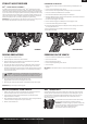
FORD
®
RAPTOR BAJA REY
®
: 1:10 4WD RTR • INSTRUCTION MANUAL
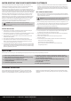
INSTALLING THE BATTERY
1. Ensure the ESC is powered OFF.
2. Slide the button to the right to release the battery door.
3. Install the fully charged battery in the vehicle.
4. Connect the battery to the ESC.
5. Close the battery door and slide the battery door button to the left to secure it.
6. Power ON the transmitter, then the vehicle.
SPEKTRUM™ DX2E RADIO SYSTEM
4
FORD
®
RAPTOR BAJA REY
®
: 1:10 4WD RTR • INSTRUCTION MANUAL
EN
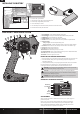
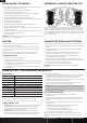
1
2
3
4
5
6
7
8
10 11
9 12
13
INSTALLING THE TRANSMITTER BATTERIES
1. Push in the battery cover a small amount to release the retaining tab, then remove the cover.
2. Install 4 AA batteries, taking care to align the battery polarity to the diagram in the
transmitter’s battery case.
3. Carefully reinstall the battery cover by aligning the tabs with the slots on the transmitter.
For more information on the transmitter, go to www.horizonhobby.com and click
on the support tab for the Spektrum DX2E to download the instruction manual.
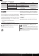
SRS6000 AVC TECHNOLOGY RECEIVER
AUX CHANNELS
The Aux channels can operate as additional servo channels, or as a power supply for a
personal transponder.
If AVC is active, only 4 channels; Steering, Throttle, AUX3 and AUX4 are operational.
The remaining Aux channels can be used to power a personal transponder or lights.
If AVC is disabled (see DISABLING THE STABILITY ASSIST FUNCTION), all 6 channels
including the Aux channels can operate as servo channels.
Antenna
Bind/Battery
Aux 4/Disable
Aux 3
Aux 2
Aux 1
Throttle
Steering
CAUTION: If using rechargeable batteries, charge only rechargeable batteries.
Charging non-rechargeable batteries may cause the batteries to burst, resulting in
injury to persons and/or damage to property.
CAUTION: Risk of explosion if battery is replaced by an incorrect type. Dispose of
used batteries according to national regulations.
CAUTION: Never remove the transmitter batteries while the model is powered ON.
Loss of model control, damage, or injury may occur.
1. Steering Wheel Controls direction (left/right) of the model
2. Throttle Trigger Controls speed and direction (forward/brake/reverse) of the model
3. BIND Button Puts the transmitter into Bind Mode
4. ON/OFF Switch Turns the power ON/OFF for the transmitter
5. TH.REV Reverses function of the speed control when pulled back or pushed forward
6. Indicator Lights
- Solid green light—indicates adequate battery power
- Flashing green light—indicates the battery voltage is critically low. Replace batteries
7. ST. REV Reverses the function of the steering when the wheels is turned left or right
8. ST Trim Adjusts the steering center point
9. TH Trim Adjusts the throttle neutral point
10. TH Limiter Limits throttle output to 50, 70 or 100%.
11. 3-Position Switch Used to control a third channel and is preset at -100%/Neutral/100%
12. ST Rate Adjusts the sensitivity of AVC technology
13. Antenna Transmits the signal to the model