
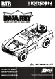
LOS03020T1 Losi Baja Rey Ford Raptor Manual

EN
6
FORD
®
RAPTOR BAJA REY
®
: 1:10 4WD RTR • INSTRUCTION MANUAL
EN
TEN-SCBE RTR, AVC: 1:10 4WD SCBE • INSTRUCTION MANUAL
DISABLING AVC
®
TECHNOLOGY
If you participate in organized racing, you may be required to turn AVC off. To turn AVC off:
1. Insert a Bind Plug in the BIND port on the receiver.
2. Insert a second Bing Plug in the DISABLE port on the receiver.
3. Connect a fully charged battery pack to the ESC.
4. Power on the ESC. The orange LED flashes, indicating the receiver is in bind mode.
5. Center the ST TRIM and TH TRIM dials on the transmitter.
6. Press and hold the BIND button while powering on the transmitter.
7. Release the BIND button when the orange LED slowly flashes. The transmitter and receiver
are linked when the orange LED is solid.
8. Pull the transmitter trigger to Full Throttle.
9. Push the transmitter trigger to Full Brake, then return the trigger to center.
10. Turn the transmitter steering wheel to Full Right.
11. Turn the transmitter steering wheel to Full Left, then return the steering wheel to center.
The orange LED flashes once.
12. Remove the Bind Plugs, then power off the receiver to save the settings. The receiver will
continuously blink to indicate AVC is disabled.
13. Power off the transmitter.
IMPORTANT: You must calibrate the receiver each time it is placed in bind mode. To activate
AVC, see the steps in “Calibrating the Receiver.”
RUN TIME
The largest factor in run time is the capacity of the battery pack. A larger mAh rating
increases the amount of run time experienced.
The condition of a battery pack is also an important factor in both run time and speed.
The battery connectors may become hot during driving. Batteries will lose performance
and capacity over time.
Driving the vehicle from a stop to full speed repeatedly will damage the batteries
and electronics over time. Sudden acceleration will also lead to shorter run times.
TO IMPROVE RUN TIMES
• Keep your vehicle clean and well maintained.
• Allow more airflow to the ESC and motor.
• Change the gearing to a lower ratio. A lower ratio decreases the operating temperature
of the electronics. Use a smaller pinion gear or larger spur gear to lower the gear ratio.
• Use a battery pack with a higher mAh rating.
• Use the optimum charger to charge battery packs. (Visit your local hobby dealer for
more information.)
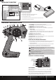
PERFORMING A CONTROL DIRECTION TEST
Perform a control test with the vehicle wheels off the ground. If the wheels rotate after the
vehicle is powered ON, adjust the TH TRIM knob until they stop. To make the wheels move
forward, pull the trigger. To reverse them, wait for the wheels to stop, then push the trigger.
When moving forward, the wheels should maintain a straight line without any steering wheel
input. If not, adjust the ST TRIM knob, so the wheels maintain a straight line without having
to turn the steering wheel.
CHANGING THE TRAVEL ADJUST SETTINGS
1. Hold the trigger in the full brake position and turn the steering wheel to Full Right while
powering on the transmitter. The LED flashes rapidly, indicating the programming mode is
active.
2. Throttle End Point: Continue holding full throttle. Turn the TH TRIM knob to adjust
the full throttle end point.
3. Brake End Point: Hold the trigger in the full brake position. Turn the TH TRIM knob
to adjust the full brake end point. Return the trigger to the center position.
4. Left Steering End Point: Hold the steering wheel in the full left position. Turn
the ST TRIM knob to adjust the left end point.
5. Right Steering End Point: Hold the steering wheel in the full right position. Turn the ST
TRIM knob to adjust the right end point. Return the steering wheel to the center position.
6. Power off the transmitter to save the travel adjust settings.
The minimum travel is 75%, and the maximum travel is 150%.
IMPORTANT: If the travel is changed on the DX2E, you must rebind and calibrate
the receiver.
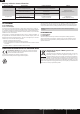
SPECIFICATIONS
Type Sensorless
Constant/Peak 130A/760A
Resistance 0.0004 Ohm
Function Forward/Brake–Forward/Brake Reverse
Operation Proportional forward, proportional reverse with braking delay
Input Voltage 7.4V–14.8V (The motor in this vehicle will not support 14.8V.)
BEC Output 6V/3A
Overload Protection Thermal
Dimensions (LxWxH) 53.5mm x 36mm x 36mm
Weight 79 g
ESC LED STATUS
• No ESC LEDs will glow when there is no throttle input from the transmitter.
• The red ESC LED glows when there is any throttle input from the transmitter.
AUDIBLE WARNING TONES
1. Input Voltage: The ESC checks the in put voltage when it is powered ON. If a voltage
problem is detected, the ESC continuously sounds 2 beeps with a 1 second pause
(xx-xx-xx). Power OFF the ESC and ensure the connections are secure and that
the battery power is not too low for safe operation.
2. Radio Connection: The ESC checks radio signal input when it is powered ON.
If a problem is detected, the ESC continuously sounds 1 beep with a 2 second pause
(x--x--x). Power OFF the ESC and ensure the radio system is operating correctly.
DYNAMITE
®
FUZE™ 130A SENSORLESS BRUSHLESS ESC
For sensorless brushless motors:
1. Connect the ESC terminal A (typically designated by a blue wire) to the motor’s terminal
A (red wire on a Dynamite
®
Fuze™ sensorless motor). This may also be changed in
Programming Item 12, Motor Rotation, without changing wire connections.
2. Connect the ESC terminal B (typically designated by a yellow wire) to the motor’s terminal
B (blue wire on a Dynamite
®
Fuze™ sensorless motor).
3. Connect the ESC terminal C (typically designated by an orange wire) to the motor’s
terminal C (black wire on a Dynamite
®
Fuze™ sensorless motor).
NOTICE: Always disconnect the battery from the ESC when you have finished operating
your vehicle. The ESC’s switch only controls power to the receiver and servos. The ESC
will continue to draw current when connected to the battery, resulting in possible dam-
age to the battery through over discharge.
ESC CALIBRATION PROCEDURE
Ensure proper ESC function by calibrating the ESC to your transmitter inputs.
1. Power OFF the ESC.
2. Ensure your transmitter is powered ON, the throttle is not reversed, the throttle trim is
neutral and the throttle travel range is at 100%. Disable any special functions such as
ABS, etc.
3. Press the SET button while powering ON the ESC. Release the button as soon as the red
LED starts to flash.
4. Calibrate the throttle points by pressing the SET button once after each step.
- Neutral (1 flash)—leave the throttle at rest, untouched
- Full throttle (2 flashes)—pull the throttle fully back
- Full brake/reverse (3 flashes)—push the throttle fully forward
5. The motor will run 3 seconds after the last step is completed.
Tip: If the motor turns in the wrong direction, reverse the connection of any 2 outside
motor wires. The center wire must remain in the center and cannot be moved to another
motor tab.
6
FORD
®
RAPTOR BAJA REY
®
: 1:10 4WD RTR • INSTRUCTION MANUAL
EN