
Instruction Manual

1/10-scale Xcelorin Brushless Electronic Speed Control
(Sensored and Sensorless)
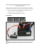
Wiring (connection) diagram for the 1/10 Xcelorin Electronic Speed
Control (ESC). With the pin and connector side of the ESC facing you:
• Switch connector should be plugged in to position 1 thru 3.
• Receiver connector in position 4 thru 6.
• Cooling fan connected using pins 7 and 8.
Pin Positions:
Note:
It is important to remember that when the connectors are plugged in
properly the gold tabs will be facing away from the ESC as shown
above.
On / Off Switch Receiver Wire
Fan
1 – Red 4 – Brown 7 – Black
2 – Orange 5 – Red 8 - Red
3 - Brown 6 - Orange