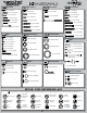
setup sheet 8IGHT-T 2.0 Race Roller Vehicle Setup 2 degrees of toe-out Differentials Front: x Standard 39mm Smart Spring Wire Dia: -1 degree Qty of Springs: Stock Ramp Plate: 2.3mm Grease: Diff Fluid: 7000 wt Losi 55/35 wt Black 3.4 lbs Center: x Standard 110mm Long Down Smart Spring Wire Dia: Qty of Springs: Ramp Plate: 2/A Grease: 2/Middle Diff Fluid: 10000 wt Losi Losi LiPo 3.5 degrees 3 degrees 42mm -2 degrees 1 spacer foward 2.
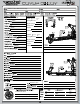
INTRO q STEP I-01 Intro to the 8IGHT-T 2.0™ Manual Welcome Team Losi Racing 8IGHT-T 2.0 Owner! Thank you for selecting the 8IGHT-T 2.0 as your new racing truggy. The 8IGHT-T 2.0 has already distinguished itself as a top caliber racing chassis and as you will see, we have made every effort to produce a vehicle that is not only the most competitive but also easy to maintain.
setup sheet Differentials Front: Standard Smart Spring Wire Dia: Qty of Springs: Ramp Plate: Grease: Diff Fluid: Center: Standard Smart Spring Wire Dia: Qty of Springs: Ramp Plate: Grease: Diff Fluid: 40
HARDWARE Cap Head Flat Head 1 2-56 x 1/4" (A6232) Flat Head 2 3 x 8mm (A9106) 2-56 x 1/2" (A6254) Button Head 2-56 x 1/4" (A6255) 8-32 x 3/8" (A6264) 4-40 x 1/4" (A6234) 3 x 12mm (A3500) 4-40 x 3/8" (A6206) 5-40 x 3/8" (A6270) 4-40 x 1/2" (A6204) 4-40 x 5/8" (A6221) 5-40 x 3/8" (A6277) 5-40 x 1/2" (A6271) 5-40 x 1/2" (A6240) 4-40 x 1/2" (A6256) 8-32 x 1/2" (A6262) 5-40 x 1/2" (A6278) 5-40 x 1-7/8" (A6273) 5-40 x 3/4" (A6279) 5-40 x 5/8" (A6275) 5-40 x 7/8" (A6282) 5-40 x 3/4" (A6272)
INTRO TOOLS REQUIRED FOR ASSEMBLY Team Losi Racing has supplied all necessary Allen wrenches and special wrenches that are needed for assembly and adjustments. The following common tools will also be required: needle-nose pliers, regular pliers, hobby knife, scissors or other body cutting/trimming tools, and a soldering iron may be necessary for radio installation. 3/16", 1/4", 5/16" and 11/32" nut drivers are optional. RADIO/ELECTRONICS A suggested radio layout is provided in this manual.
STEP A q STEP A-01 q STEP A-02 Steering Link Assembly Servo Saver Assembly x1 x1 A9168 Steering Servo Arm 4-40 x 1/2" A6256 A4407 Servo Saver Tube L 4-40 x 3/16" A6306 Maintenance Tip A6044 Rod End Ball A6044 Rod End LOSI-LOK x1 L 4-40 x 3/16" A6306 A4406 Steering Arm A4412 Steering Rack x1 4-40 x 1/2" A6256 A4412 Drag Link Screw x1 5-40 x 7/8" A6537 A4406 Steering Bellcrank R A4406 Steering Bellcrank L A4423 Servo Saver Spring 73.
STEP A q STEP A-04 Steering/Top Plate Assembly x1 LOSI-LOK A4413 Front Chassis Brace 5-40 x 1/2" A6271 LOSI-LOK x2 5-40 x 1/2" A6278 x4 6x10x3mm A6946 q STEP A-05 Completed Steering Assembly 2
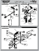
STEP B q STEP B-01 q STEP B-03 Ring Gear Assembly Complete Diff Assembly A3503 Outdrive Cup Solid x1 Fill with 7000 wt oil just above the planetary gear 2.5 x 12.80mm A3503 1 x4 3 3x12mm A3500 2 x1 F 8x14x4mm A6948 A3511 Ring Gear 4 A3505 O-ring A3502 Sun Gear x2 A3505 Diff Seal 6x11x0.2mm A3501 q STEP B-02 A3502 Planetary Gear Diff Case Assembly A3502 Planetary Gear Axle Solid x1 2.5 x 12.
STEP B q STEP B-04 Front Diff Install x1 F 8-32 x 1/8" A6296 To prevent fine dust from entering the gearbox, apply a thin bead of grease along the edge of the case as pictured. 3 LOSI-LOK 4 A3514 Drive Adapter x2 5x11x4mm A6947 1 2 6 x2 A4427 Front Diff Case A3507 Pinion Gear, Bevel 5-40 x 7/8" A6273 5 x2 5-40 x 1/2" A6240 A4427 Front Diff Cover q STEP B-05 Front Spindle & CV Assembly A3586 Front Driveshaft Solid x1 2.5 x 12.
STEP B q STEP B-06 Spindle/Carrier Assembly x1 O 10-32 x 3/8" A6295 x2 A1705 Shoulder Bushing A1704 Left Front Arm 8-32 x 5/8" A6266 5 A6501 Hinge Pin 2 x2 8-32 x 3/4" A6263 4 4 x2 1 C 5-40 x 1/8" A6299 5 A1701 Arm Bushing 3 A1709 Front Spindle Carrier 3 2 q STEP B-07 Front Suspension Arms Assembly A4431 Front Inner Hinge Pin Cap A1744 Front Inner Hinge Pin Brace Solid x2 4 x 65mm A6500 x4 5-40 x 3/4" A6272 A4431 Front Outer Hinge Pin Cap A1744 Front Outer Hinge Pin Brace 5
STEP B q STEP B-08 Sway Bar Assembly A1750 Sway Bar Link Install the Sway Bar Ball onto the Sway Bar Wire until the end of the wire is flush with the ball as pictured above.
STEP B q STEP B-10 Center CV Assembly x4 5-40 x 5/8" A6275 A6050 Steering Ball A6547 4mm x 114mm Turnbuckle A6046 Steering Rod End 137.20 x2 5-40 x 1/4" A6302 q STEP B-11 Steering Rod Assembly Be sure to install the assembled Tie Rod onto the car with the groove (next to the center square section) on the driver’s left side for easier adjustment later. 3 Solid x2 x2 2.
STEP B q STEP B-12 Front Clip Assembly x2 5-40 x 3/4" A6279 x2 5-40 x 3/4" A6272 4 1 A4453 Front Bulkhead Spacer 3 2 x4 8-32 x 1/2" A6262 A4422 Front Bumper q STEP B-13 Completed Front Assembly 8
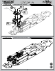
STEP C q STEP C-01 q STEP C-03 Ring Gear Assembly Solid Fill with 10000 wt oil just above the planetary gear. x1 2.5 x 12.80mm A3503 3 Complete Diff Assembly x4 A3502 Sun Gear 3x12mm A3500 1 2 4 A3506 Center Outdrive x2 x1 6x11x0.2mm A3501 F 8x14x4mm A6948 A3505 O-ring A3515 50T Spur Gear A3505 Diff Seal A3502 Planetary Gear Axle q STEP C-02 Solid A3502 Planetary Gear Diff Case Assembly x1 2.5 x 12.
STEP C q STEP C-04 q STEP C-05 Center Top Brace Assembly (.5mm)(.020”) x2 F 5-40 x 1/8" A6297 5mm E-clip A6109 A9168 Threaded Servo Rod A9168 Rear Brake Rod x1 LOSI-LOK Linkage Assembly A9168 Front Brake Actuator x1 A9168 Throttle Rod End 2-56 x 1/2" A6254 LOSI-LOK x2 x1 .250x.
STEP C q STEP C-08 Brake Caliper Assembly A3546 Front Brake Pad A3546 Rear Brake Pad .307” 7.
STEP C q STEP C-10 Center Diff Installation Caution! Ensure that the driveshaft is inserted into the slot of the center outdrive while installing the Center Diff assembly.
STEP D q STEP D-01 Solid q STEP D-03 Ring Gear Assembly Complete Diff Assembly x1 Fill with 2000 wt oil just above the planetary gear. 2.5 x 12.80mm A3503 3 1 A3502 Sun Gear x4 2 3x12mm A3500 A3503 Outdrive Cup A3505 Diff Seal x1 A3505 O-ring 4 F 8x14x4mm A6948 x1 6x11x0.2mm A3501 A3502 Planetary Axle A3512 Rear Ring Gear A3502 Planetary Gear q STEP D-02 Diff Case Assembly Solid x1 2.5 x 12.80mm A3503 A3502 Sun Gear 3 A3500 Diff Housing Tighten the diff screws in this order.
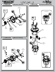
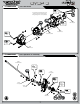
STEP D q STEP D-04 Rear Diff Installation x1 A4414 Rear Chassis Support x1 F 8-32 x 1/8" A6296 5-40 x 7/8" A4414 A4451 Rear Gearbox Locking Insert x2 A3514 Drive Adapter x1 14x17x0.25mm A4452 14x17x0.10mm A4452 x2 3 2 x1 L 5-40 x 1/4" A6302 A3507 Pinion Gear x2 A4450 Rear Gearbox 5-40 x 7/8" A6273 6 q STEP D-05 A4451 Rear Gearbox Locking Insert 5 The 8T 2.0 comes with (2) .25mm shims and (1) .10mm shims on the left bearing insert. On the right bearing insert there are (3) .10mm shims.
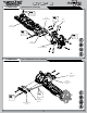
STEP D q STEP D-06 Rear Suspension Arm Assembly A1743 Rear Outer Hinge Pin Brace 3.5T/3A x2 5-40 x 1-7/8" A6273 A4431 Rear Outer Pivot Brace Cap x2 O 10-32 x 3/8" A6295 A1726 Left Rear Arm Solid x2 x2 4 x 66mm A6500 5/40 x 3/4" A6272 A1745 Rear Inner Hinge Pin Brace Solid x2 3.5 x 53mm A6503 A4431 Rear Inner Pivot Brace Cap x2 L 5-40 x 1/4" A6302 q STEP D-07 A4453 Hub Spacer .050” Sway Bar Assembly A1750 Rear Sway Bar, 2.
STEP D q STEP D-08 Wing Mount Assembly A4435 Wing Mount Brace A4435 Right Wing Mount x2 5-40 x 1/2" A6240 x2 x3 x4 L 5-40 x 1/4" A6302 5-40 x 1/2" A6278 5-40 x 3/4" A6279 A4435 Left Wing Mount A4433 Rear Body Mount x2 A1740 Rear Shock Tower q STEP D-09 A5438 Shock Stand-Off L 8-32 x 11/32" A6311 Rear Shock Tower Installation x2 5-40 x 3/4" A6279 x2 5-40 x 1/2" A6278 16
STEP D q STEP D-10 Tie Rod Installation A6048 A6545 A6047 x2 5-40 x 3/4" A6279 x2 5-40 x 1/4" A6302 142 x2 5-40 x 1" A6280 Center CV Assembly Solid x1 2.
STEP D q STEP D-12 Rear Clip Assembly x2 L 5-40 x 1/4" A6302 Caution! Ensure that the driveshaft is inserted into the slot of the center outdrive while installing the Rear Clip assembly.
STEP E q STEP E-01 • • • • • • • • • • • • • • Shock Assembly Clean the 2-56 x 1/4" Button Head Screw and apply Losi-Lok to the threads. Install the #55 Shock Piston on the front shock shaft and a #56 Shock Piston on the rear shock shaft using the 2-56 x 1/4" Button Screw into the Shock Shaft with a .050" Allen Wrench. Place a drop of Shock Oil into the bottom of the Shock Body to lubricate the Shock Seals. Thread the Shock Shaft into the Shock End using pliers.
STEP E q STEP E-02 x2 x2 Front Rear Shock Boot & Spring Assembly Front Rear A5426 Shock Boot A5427 Shock Boot A5459 Black Front Spring A5461 Gray Front Spring A5435 Spring Cup q STEP E-03 A5435 Spring Cup Front Shock Installation A5435 Shock Mount Bushing x2 L 5-40 x 1/4" A6302 x2 5-40 x 7/8" A6282 20
STEP E q STEP E-04 Rear Shock Installation A5435 Shock Mount Bushing x2 L 5-40 x 1/4" A6302 x2 5-40 x 7/8" A6282 q STEP E-05 Completed Shock Assembly 21
STEP F q STEP F-01 Chassis Guard Installation A4438 Chassis Guard A4438 Chassis Guard x7 5-40 x 3/8" A6270 q STEP F-02 Switch Installation Supplied with switch (not included) x3 Optional Blank Switch Mount Plate If not using a switch, install the optional Blank Switch Mount Plate in place of the Switch Plate.
STEP F q STEP F-03 Servo Chart/Wiring Diagram Servo Spacer Servo Horn All (DZ9100T/S Needs Spacer) No 23T 94357Z, 94358Z, 94649Z, 94360Z, 94452Z, 94758Z, 94737Z, 94738Z Yes 94102Z, 94112Z Yes All No Servo Manufacturer, Make/Model JR Steering Servo Wires Sanwa Airtronics 23T Hitec Futaba All (S9102 DOES NOT FIT) 24T No 25T KO PROPO No PDS-2123, 2344, 2363, 2365, 2366 Throttle Servo Wires Switch Wires 23T No Table2: Servo assembly and installation Airtronics® is a registered ma
STEP F q STEP F-05 Steering Servo Installation x4 A9168 Horn Insert 4-40 x 1/2" A6204 x4 #4 x .
STEP F q STEP F-07 Receiver Battery Door x2 Optional Battery Covers High Profile Cover should be used with the Hump pack type receiver packs. Low Profile Cover should be used with the LiPo type receiver packs.
STEP F q STEP F-09 Servo Horn Installation Supplied with servo (Not Included) Ensure the servo gear is centered before attaching the Servo Horns. This is best accomplished by connecting the servos to the radio system and setting the trim to center.
STEP G q STEP G-01 Clutch Assembly A9108 Aluminum Clutch Shoe A9114 Clutch Spring Gold Aluminum Shoe LOSI-LOK A9105 Aluminum Flywheel A9105 Flywheel Collet 1 A9113 Clutch Spring Green Aluminum Shoe 2 A9108 Aluminum Clutch Shoe A9103 Clutch Nut A9106 Clutch Pins q STEP G-02 Clutch Bell Assembly Use the appropriate number of shims to achieve proper clutchbell end play. Generally .25mm to .50mm is x2 optimum. 5x7x0.2mm A6356 x1 5x13x4mm A6949 x1 A9106 Clutch Spacer 5x7x0.
STEP G q STEP G-03 Engine Mount Assembly x4 LOSI-LOK 5-40 x 1/2" A6240 x4 Ball Stud A6215 Pipe/Header (Not supplied) A9154 Right Engine Mount q STEP G-04 A9154 Left Engine Mount Air Filter Assembly Tech Tip With a clean rag or paper towel take the air filter and squeeze it between the rag to remove any excess air filter oil. The goal is to remove all the oil blotches from the filter to improve engine performance.
STEP G q STEP G-05 Air Filter Installation 1 2 q STEP G-06 Pipe Mount Assembly x1 8-32 x 1/8" A6298 Trim pipe mount in small increments as needed to mount pipe. Ensure that the wire clears all steering components.
STEP G q STEP G-07 • • • • Engine Installation Adjust the gear mesh between the Clutch Bell and the Spur gear by sliding the engine mounts in the slots of the chassis. In order to function properly, the Gears should be as close as possilbe, but still have a small amount of backlash (space between the Gear teeth). Place a piece of paper between the Clutch Bell gear and Spur gear, slide the engine sideways until the paper is pinched between the gears and tighten the engine mount screws.
STEP H q STEP H-01 Tire Mounting 1 2 A7780B XBT™, Blue 1/8 Truggy Foam Insert. Only sold with Tires. A7747 1/8 Truggy Wheel q STEP H-02 • • Tire Gluing The tires are already glued to the wheels. Here are the steps to show you how to complete this process. This can be done by using a fast-curing super glue or cyanoacrylate glue (LOSA7880, LOSA7881), available at your local hobby shop. Install a tire gluing rubber band around the outside of the tire, in line with the bead to hold it onto the wheel.
STEP H q STEP H-03 Tire Installation A3531 Wheel Hex LOSI-LOK A3531 Wheel Hex LOSI-LOK q STEP H-04 Wing Installation A8130 Wing Button 1 x2 Body Clip A8200 2 A8130 Rear Wing 32
STEP H q STEP H-05 Completed Chassis Assembly 33
Checklist BEFORE RUNNING YOUR NEW 8IGHT-T 2.0 OFF-ROAD RACING Truggy for the first time, you should run down the following checklist in order and complete the listed tasks. We’re sure you’re anxious to get out and run your new 8IGHT-T 2.0 now that it’s built, but please note that fine-tuning of the initial setup is an essential part of building a high-performance racing truggy such as your new 8IGHT-T 2.0.
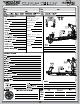
SETUP GUIDE TIPS AND HINTS FROM THE TEAM Before you start making changes on your 8IGHT-T 2.0 Off-Road Racing truck, you need to make a few decisions. First of all, tires, and how they are setup, have a tremendous impact on overall performance. Before you start making changes on the chassis setup, take a moment to observe a few of the fastest cars at the track and what type of tire and inner liner they are running.
SETUP GUIDE The 8IGHT-T 2.0 is equipped with the rear hub carriers in the middle. A shorter wheelbase (spacers behind the rear hubs) increases on-power traction, rear weight transfer, and has more off-power steering. A shorter wheelbase is better on tight or slick tracks. A longer wheelbase (spacers in front of the rear hubs) decreases off-power steering, is more stable, better in bumps, and has more on-power steering. Sway Bars: The 8IGHT-T 2.0 is equipped with 2.3mm sway bars on the front and rear.
SETUP GUIDE short Ackerman plate responds quicker and has more steering in the middle of the turn. A short Ackerman plate is better suited for tight technical tracks. Camber: More negative camber in the front has more steering and is more responsive. Less negative camber in the front will have less steering and will be smoother. More negative camber in the rear will have less rear traction, but will increase on-power steering and will be less grabby in bumps.
warranty Warranty Period Horizon Hobby, Inc., (Horizon) warranties that the Products purchased (the “Product”) will be free from defects in materials and workmanship at the date of purchase by the Purchaser. Limited Warranty (a) This warranty is limited to the original Purchaser (“Purchaser”) and is not transferable. REPAIR OR REPLACEMENT AS PROVIDED UNDER THIS WARRANTY IS THE EXCLUSIVE REMEDY OF THE PURCHASER. This warranty covers only those Products purchased from an authorized Horizon dealer.
warranty United States: Electronics and engines requiring inspection or repair should be shipped to the following address: Horizon Service Center 4105 Fieldstone Road Champaign, Illinois 61822 All other Products requiring warranty inspection or repair should be shipped to the following address: Horizon Product Support 4105 Fieldstone Road Champaign, Illinois 61822 Please call 877-504-0233 or e-mail us at productsupport@horizonhobby.com with any questions or concerns regarding this product or warranty.