
Instruction Manual


15
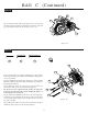
Figure 35
BAG C (Continued)
Figure 35
Figure 36
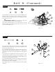
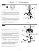
Step 24. Press the 1/16" x 5/16" pin (74) into the small hole in the
slipper shaft (73) so that it extends evenly from both sides of the shaft
(73).
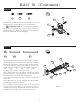
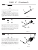
Step 25. Slide the top gear (75) over the setscrew (72) onto the slipper
shaft (73). Align the groove in the gear (75) with the pin (74) and slide
the gear (75) over the pin (74).
Step 26. Secure the top gear (75) to the shaft (73) by inserting a 3/16"
C-clip (76) into the groove in the slipper shaft (73).
Figure 37
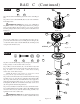
Step 23. Locate the slipper shaft (73) and thread the 4-40 x 1" setscrew
(72) all the way into the threaded side of the slipper shaft (73). Make
sure that the setscrew (72) is TIGHT!
*NOTE: Some top gear/slipper shaft assemblies may be pre-
assembled from the factory.
Tip: A small amount of liquid thread-lock should be used to help to
hold the setscrew securely in place. If your slipper shaft was pre-
assembled at the factory, thread-lock compound has already been
applied.
Figure 36
Figure 37
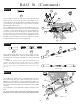
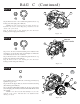
Step 27. Locate the brake shaft (77) and press the .078" x 3/8" spirol
pin (78) into the small hole away from the grooved end of the brake
shaft (77) so that it extends evenly from both sides of the shaft (77).
Step 28. Press the compound gear bushing (181) all the way into the
end of the compund gear (79). Slide the compound gear (79), with the
bushing (181) in place, over the brake shaft (77). Align the groove in
the gear (79) with the pin (78) and slide the gear (79) over the pin (78).
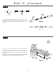
Step 29. Secure the compound gear (79) and bushing (181) to the
shaft (77) by inserting a 3/16" C-clip (76) into the groove in middle of
the brake shaft (77).
7
6
7
6
78
72
7
4
73
72
73
76
74
75
76
79
78
77
18
1