
Installation Guide

www.factorybuysdirect.com
19200302-01C
OPERATION
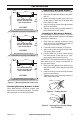
THERMOSTAT CONTROL OPERATION
The thermostatic control used on this model
differs from standard thermostats. You set
standard thermostats to a specic tempera-
ture such as 72 degrees. The thermostat
used on this heater senses the room tem-
perature. At times the room may exceed the
set temperature. If so, the burner will shut
off. The burner will cycle back on when room
temperature drops below the set temperature.
The control knob can be set to any comfort
level between HIGH and LOW.
Note: The thermostat sensing bulb reacts
to the temperature depending on housing
construction.
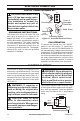
TO TURN OFF GAS TO APPLIANCE
Shutting Off Heater
Turn control knob clockwise to the
OFF position.
Shutting Off Burner Only
(pilot stays lit)
Turn control knob clockwise to the
PILOT position.
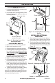
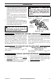
MANUAL LIGHTING PROCEDURE
1. Remove front panel.
2. Follow steps 2 through 5 under Lighting
Instructions, page 18.
3. With control knob pressed in, strike match.
Hold match to pilot until pilot lights.
7. Keep control knob pressed in for 30 sec-
onds after lighting pilot. After 30 seconds,
release control knob. If control knob does
not pop up when released, contact a quali-
ed service technician or gas supplier for
repairs.
Note: If pilot goes out, repeat steps 2
through 6. This heater has a safety inter-
lock system. Wait one (1) minute before
lighting pilot again.
8. Turn control knob counterclockwise
to desired heating level. The main burner
should light. Set control knob to any heat
level between HIGH and LOW.
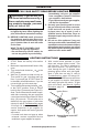
CAUTION: Do not try to ad-
just heating levels by using the
equipment shutoff valve.
WARNING: If input gas
type is NG, make sure NG pilot
burner ignites. If input gas type
is LP, make sure LP pilot burner
ignites.
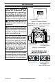
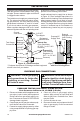
Figure 22 - Pilot
Pilot Air
Inlet Hole
Natural Gas
Burner
Propane/LP
Gas Burner
Thermocouple
Pilot Air Inlet Hole
Ignitor
Electrode
4. Keep control knob pressed in for 30 sec-
onds after lighting pilot. After 30 seconds,
release control knob. Follow step 8 under
Lighting Instructions, page 18.
5. Replace front panel.