ATTIC LADDER INSTALLATION INSTRUCTIONS INSTRUCCIONES DE INSTALACIÓN DE LA ESCALERA DE ÁTICO English / Inglés: Page 1 / Página 1 | Español / Spanish: Página 12 / Page 12 MODELS/MODELOS: AA2210 | AA2510 | WA2210
WARNING Before you start installing your new Louisville Ceiling Mounted Folding Attic Ladder, you must read and understand the following: 1. For residential use only. Not for use in a commercial or industrial setting. 2. Installation requires two people. 3. Do NOT remove plastic straps holding the ladder sections together until instructed. 4. Check the ceiling height to make sure the ladder length is correct. If the ladder is too short, return it to the point of purchase for an exchange.
Included with your Folding Attic Ladder: WOOD SERIES NO. ITEM QTY 1 Pull cord 36” 1 2 Deck screw 2 1/2” 8 3 Lag screw 3” 10 4 Plastic Shoe 2 5 Wood screw 1” 4 FIGURE 1: Wood series ALUMINUM SERIES NO. ITEM QTY 1 Pull cord 36” 1 2 Deck screw 2 1/2” 8 3 Lag screw 3” 10 4 Aluminum Feet (mounted on ladder) 2 5 1/4” Nuts (mounted on ladder) 4 6 Bolts ¼” x ¾” large (mounted on ladder) 4 FIGURE 2: Aluminum series MATERIALS REQUIRED 1. Stepladder 7. Drill 2. Hammer 8.
INSTALLATION INSTRUCTIONS FOR WOOD MODELS AND FOR ALUMINUM MODELS READ INSTRUCTIONS AND WARNINGS COMPLETELY BEFORE STARTING IMPORTANT: Do not open folding attic ladder until instructed to in step number 3. FOLDING ATTIC LADDER LOCATION: Allow ample room for the swing clearance and the landing space of the folding attic ladder when it is opened (see Figure 3 and table 1). Locate the folding attic ladder rough opening so that when you enter the storage area, you will have adequate head clearance.
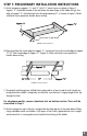
STEP 1: PRELIMINARY INSTALLATION INSTRUCTIONS A. Attach temporary supports “A” and “B” with 2 ½” deck screws as shown in Figure 4. Support “A” should be located at the end where the door hinge of the ladder will go. The edge of support “A” should extend into the rough opening 3/8” as shown in Figure 5. Make sure both screws penetrate header above ceiling. Deck screw (2) per board FIGURE 4: View from below B.
E. The person below will need to raise the attic ladder into the rough opening and with assistance from person above position securely on the temporary support boards (Figure 6). Support B Support A FIGURE 6 F. Make sure frame on door hinge side of ladder is pushed up against header and is centered side to side in rough opening. Temporarily secure frame to header using two 2 ½” deck screws (Figure 7). Do not use pre–drilled holes for deck screws. Pre–drilled holes are used in Step 2.
STEP 2: PERMANENT INSTALLATION A. The ladder comes with pre–drilled holes for permanent installation at locations shown in Figure 8 for wood models and Figure 9 for aluminum models. Shim, when necessary to fill space between ladder frame and rough opening, at pre–drilled locations. Using 1/8” drill bit, drill pilot holes through shim into ceiling joists and header. FIGURE 8: Wood series FIGURE 9: Aluminum series B.
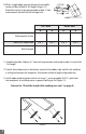
B. With a straight edge, measure distances from middle section to floor, for both A & B lengths (Figure 11). Record the results in the space provide in table 2. Take measurements for both the left and right rails. CUTTING LINE FIGURE 11 LEFT RAIL RIGHT RAIL A B A B (-1/4”) (-1/4”) (-1/4”) (-1/4”) Measurement to floor Subtract for rubber shoe Rail cut length TABLE 2 C. Complete the table: Subtract 1/4” from each measurement and record in table 2 in row titled “Cut Length” D.
ALUMINUM MODELS ONLY: A. Using a tape measure double check the height of the ceiling. B. Determine the location to cut the ladder and ladder feet for your ceiling height from table 3.
E. Slide aluminum foot over ladder rail as shown in Figure 14. Position so the rubber foot is in contact with the floor. Align with closest set of predrilled holes in rail. Attach using (2) 1/4” bolts and serrated nuts per side (included). FIGURE 14 Check the length after making your cuts Again, be sure the attic ladder power arms are fully extended. Trimmed correctly, your attic ladder should look like Figure 16. Verify that there are no gaps in the section and both feet are flat on the floor.
APPENDIX – Framing A Rough Opening Parallel To Ceiling Joist Make a rough opening to the size as required in table 1 ensuring that the dimensions of the diagonals of the frame are the same as illustrated in Figure 18. MODEL ROUGH OPENING CEILING HT. RANGE “A” LANDING SPACE “B” SWING CLEARANCE “C” AA2510 25 1/2” x 54” 7’ 8” – 10’ 3” 67” 74” AA2210 22 1/2” x 54” 7’ 8” – 10’ 3” 67” 74” WA2210 22 1/2” x 54” 7’ 11” – 10’ 3” 64 1/2” 74” TABLE 1 (repeated from page 3) A.
(Figure 20) • Locate double headers at each end of opening and secure with (3) 16d nails into each end of the headers. • Install stringer and check for squareness by making sure that diagonals are within 1/8”. • Secure using (3) 4” nails into each end of the stringer. CAUTION: Consult an engineer or architectural approval for installations that require the removal of roof trusses or rough openings perpendicular to the ceiling joists.
ADVERTENCIA Antes de empezar la instalación de su nueva escalera de ático plegable para montaje en el techo Louisville, debe leer y entender lo siguiente: 1. Solo para uso residencial, no para uso de establecimientos comerciales o industriales. 2. La instalación requiere 2 personas 3. Favor de NO remover los cinchos de plástico que aseguran las secciones de la escalera hasta que se indique. 4. Revise que la altura del techo no sea mayor que el largo de la escalera.
Componentes Incluidos en la Escalera de ático plegable para montaje en el techo: SERIE DE MADERA NO. ARTICULO CANTIDAD 1 Cordón 36” 1 2 Pija de madera 2 1/2” 8 3 Pija hexagonal 3” 10 4 Tacón de plástico 2 5 Pija de madera 1” 4 FIGURA 1: Serie de Madera SERIE DE ALUMINIO NO.
INSTRUCCIONES DE INSTALACIÓN PARA MODELOS DE MADERA Y ALUMINIO Lea las instrucciones y advertencias completas antes de empezar IMPORTANTE: No abra la escalera de ático plegable hasta que se indique en el paso 3 UBICACIÓN DE ESCALERA PLEGABLE DE ÁTICO: Deje espacio suficientemente amplio para la apertura y descenso de la escalera plegable de ático cuando sea abierta (véalo en la Figura 3 y en la Tabla 1).
PASO 1: INSTRUCCIONES DE INSTALACIÓN PRELIMINARES A. Añada soportes temporales “A” y “B” con pijas de 2 1/2” como se muestra en la Figura 4. El soporte “A” debe estar situado en el extremo, donde se ubica la bisagra de la puerta de la escalera. El borde del soporte “A” deberá extenderse 3/8” dentro de la abertura como se muestra en la Figura 5. Asegúrese de que ambas pijas penetren el cabezal por encima del techo. Soporte “A” Soporte “B” Pijas de madera de 2 por soporte temporal FIGURA 4 B.
E. La persona que este abajo, tendrá que levantar la escalera de ático hacia la abertura del techo y deberá ser asistido por la persona en el ático, asegurando la escalera sobre los soportes temporales (Figura 6) Soporte B Soporte A FIGURA 6 F. Asegúrese que el marco en el lado de la bisagra de la escalera este presionado contra el cabezal y que este centrado de lado a lado en la abertura del techo; Asegure temporalmente el marco al cabezal usando pijas de 2 1/2” (Figura 7).
PASO 2: INSTALACION PERMANENTE A. La escalera viene con agujeros pre–perforados para instalación permanente, los agujeros para la instalación permanente se muestran en la Figura 8 para los modelos de madera y en la Figura 9 para los modelos de aluminio. Use cuñas cuando sea necesario para llenar el espacio entre el marco de la escalera y abertura en el techo, en lugares pre–perforados. Usando la broca de 1/8”, perfore orificios guía a través de cuña hasta las vigas del techo y el cabezal.
B. Mida la distancia desde la sección media al suelo a lo largo de la escalera, para las longitudes A y B (Figura 11). Registre los resultados en el espacio provisto en la Tabla 2. Tome mediciones tanto para los rieles izquierdo y derecho. LINEA DE CORTE FIGURA 11 RIEL IZQUIERDO RIEL DERECHO A B A B (-1/4”) (-1/4”) (-1/4”) (-1/4”) Medición al suelo Resta del tacón de goma Longitud de corte del riel TABLA 2 C.
SOLAMENTE PARA MODELOS DE ALUMINIO: A. Use una cinta de medir para corroborar la altura del techo. B. Determine la ubicación de corte de la escalera y de los tacones dependiendo de la altura de su techo en la Tabla 3.
E. Deslice el tacón de aluminio sobre el riel como se muestra en la Figura 14. Posiciónelo de modo que el tacón plástico esté en contacto con el suelo. Alinee el más cercano conjunto de agujeros con los agujeros perforados en el riel. Sujételo usando (2) tornillos de ¼” y tuercas dentadas por cada lado (incluidas). FIGURA 14 Revise las longitudes después de marcar los cortes De nuevo, asegúrese que los brazos de poder de la escalera de ático estén totalmente extendidos.
APENDICE – Enmarcando la abertura paralela a las vigas del techo. Haga la abertura en el techo del tamaño que se indica en la Tabla 1 asegurando que las dimensiones de las mediciones diagonales del marco son iguales como se ilustran en la Figura 18.
(Figura 20) • Coloque dos cabezales en cada extremo de la abertura y fíjelos con (3) clavos de 16d (aprox. 3 1/2” de largo) en cada extremo de cada cabezal. • Instale el larguero y compruebe la cuadratura, asegurándose de que las medidas diagonales estén dentro de 1/8” entre ellas. • Sujete con (3) clavos de 4” en cada extremo del larguero.
CAUTION | PRECAUCIÓN DO NOT REMOVE THIS STRAP UNTIL INSTRUCTED! Installation instructions inside this book NO QUITE ESTE CINCHO HASTA QUE SE INDIQUE! Instrucciones de Instalación en este libro