
- COZY/ Louisville Tin and Stove Co. Inc. INSTALLATION AND OPERATING INSTRUCTIONS Gas-Fired Vented FLOOR FURNACE 90N30A, 90N50A, 90N65A, 90N75A


ADJUSTING THE BURNER – Continued
If difficulty in adjusting the burner is experienced, it may be the result of incorrect gas supply pressure or manifold pressure.
Pressure can only be checked and adjusted by a trained service technician using instruments designed for that purpose.
WARNING: Do not attempt to change pressure settings without proper training and instruments.
To do so may cause your floor furnace to malfunction resulting in property damage, bodily injury, or
death.
The following information is provided for use by a trained service technician with measuring instruments.
Minimum Inlet Pressure, Natural Gas……………………………………………………. 4.5 Inches Water Column
Minimum Inlet Pressure, Liquefied Petroleum (L.P.) Gas……………………………….. 11.0 Inches Water Column
Maximum Inlet Pressure for Natural Gas………………………………………………… 7.0 Inches Water Column
Maximum Inlet Pressure, Liquefied Petroleum (L.P.) Gas………………………………. 14.0 Inches Water Column
(If the inlet pressure is found to exceed 14.0 inches water column, check the performance of the control valve thoroughly as
damage may have occurred. If manifold pressure cannot be adjusted, replace the control valve).
Manifold Pressure, Natural Gas………………………………………………………….. 3.5 Inches Water Column
Manifold Pressure, Liquefied Petroleum (L.P.) Gas…………………………………….. 10.0 Inches Water Column
OPTIONAL OPERATION
Your floor furnace has been designed to meet all safety requirements of the American National Standards Institute and
government regulations by offering two modes of operation.
WARNING
FLOOR FURNACE GRILLS BECOME
HOT WHEN FURNACE IS IN
OPERATION. CONTACT OF BARE
SKIN WITH GRILL MAY RESULT IN
SEVERE BURNS. KEEP CHILDREN
OFF, PROVIDE FENCE OR REGISTER
GUARD FOR THEIR PROTECTION.
LIMIT SWITCH
TEMPERATURE SETTINGS
90{N,P}30A…………………….. 140N
90{N,P}50A…………………….. 160N
90{N,P}65A…………………….. 180N
90{N,P}75A…………………….. 170N
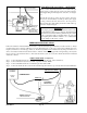
OPTION 1
In mild weather,
operate furnace
with damper open.
Furnace will cycle
on and off main-
taining a moderate
grill temperature
and an even room
temperature.
OPTION 2
In extremely cold
weather, close damper
(which exposes warning
plate). Furnace will then
put out maximum
amount of heat until
room temperature
reaches setting on wall
thermostat.
Damper
Open
FIGURE 21
Damper
Closed
FIGURE 22
Page 13
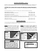
OPTION 1. Place the furnace key on the damper control
rod (See Figure 21) and turn counterclockwise
until the warning flag is concealed and the damper is
open. Your floor furnace will now cycle on and off
maintaining a moderate grill temperature and an even
room temperature. Your floor furnace will function best
on this setting during mild weather.
OPTION 2. Turn the furnace key clockwise until the
warning flag reading “WARNING – GRILL IS HOT – Keep off –
can cause burns” is visible and the damper is closed. The limit
control will now cease to function and the floor furnace will now
put out the maximum amount of heat until the room temperature
reaches the thermostat setting. Use this option only in extremely
cold weather. If furnace continues to cycle on limits, assure that
damper door is 100% closed by adjusting damper door pin if
necessary.