
- COZY INSTALLATION AND OPERATING INSTRUCTIONS Gas-Fired Vented Room Heater VC201A-H, VC202A-H, VC351A-H, VC352A-H, VC501A-H, VC502A-H, VC701A-H, VC702A-H, VCR351A-H, VCR352A-H, VCR501A-H, VCR502A-H, VCR701A-H, VCR702A-H


Page 13
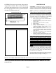
Heat Shield
Junction
Box
Speed
Control
Power
Cord
Fan Switch
Bracket
Blower
Housing
Mounting Tab
FIGURE A
CHB-3 BLOWER INSTALLATION - (OPTIONAL)
(STANDARD ON 70,000 BTU UNITS ONLY)
STEP 1. Run black wire and white wire that comes from bottom of junction box down through the heat shield. See Figure A.
STEP 2. Insert junction box into opening in back of heater. Attach using four #8x1/2” black screws provided. See Figure A.
STEP 3. Attach fan switch to fan switch bracket using two #8x1/2” plated, Phillip head screws provided. The 2” flange on the
bottom of bracket and terminals on the fan switch should be toward the back of the heater when properly installed.
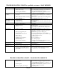
STEP 4. Locate the two engagement holes in base of heater. On a 35,000 Btu heater these holes are approximately 6-1/2” from the
back edge and right and left holes are 5-1/4” and 7-1/4” respectfully from the right side (as viewed from back of heater). On
a 50,000 Btu heater the holes are approximately 10-3/4” from the back edge and right and left holes are 5-3/8” and 7-3/8”
respectfully from the right side. Attach fan switch bracket to base using two #8x1/2” hex head screws provided. This will
require a ¼” socket and ratchet. See Figure A.
STEP 5. Locate the blower opening and mounting tab on the base of the heater. Insert the front flange of the blower housing under
the mounting tab, lower the back of the blower down onto the base aligning the clearance holes in the blower base with the
engagement holes in the heater base. Secure the blower to the base with two #8 screws provided. See figure A.
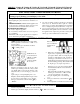
STEP 6. Connect black wire from junction box to right fan switch terminal. See Figure B.
STEP 7. Connect white wire from junction box to white fan motor wire. See Figure B.
STEP 8. Connect black wire from fan motor to left fan switch terminal. See Figure B.
STEP 9. Turn variable speed control switch clockwise (as viewed from front of unit) to “OFF”.
STEP 10. Plug power cord into 115 V. grounded receptacle.
STEP 11. Turn variable speed control switch counterclockwise (as viewed from front of unit) from “OFF” to “HIGH”. Blower
will now cycle on automatically when the switch temperature is met after the main burner comes on. The blower will
continue to run for a short period after the main burner goes off. Blower speed can be adjusted by setting the variable
speed control switch between high and low.
WARNING: This appliance is equipped with a three-prong (grounding) plug for your protection against shock hazard and should
be plugged directly into a properly grounded three-prong receptacle. Do not cut or remove the grounding prong from this
plug.
CAUTION: Label all wires prior to disconnection when servicing controls. Wiring errors can cause improper and dangerous
operation. Verify proper operation after servicing.
BLACK
BLACK
WHITE
GREEN
MOTOR SPEED
CONTROL
WHITE
BLACK
FAN
SWITCH
MOTOR
“If any part of the original wire as suppied
with the appliance must be replaced, it
must be replaced with a wire of at least
a 105 degree C temperature rating.”
FIGURE B