
- COZY INSTALLATION AND OPERATING INSTRUCTIONS Gas-Fired Vented Room Heater VC201A-H, VC202A-H, VC351A-H, VC352A-H, VC501A-H, VC502A-H, VC701A-H, VC702A-H, VCR351A-H, VCR352A-H, VCR501A-H, VCR502A-H, VCR701A-H, VCR702A-H


TSK WALL STAT KIT OPTIONAL
(VC/VCR-
H SERIES HEATERS)
WALL THERMOSTAT INSTALLATION INSTRUCTIONS
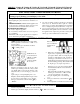
Your heater can be re-wired to operate with a millivolt wall thermostat by your installer. See wiring diagram
below for correct wiring.
NOTE: Do not disconnect the wire from the blocked flue switch to the “TH” terminal on the gas valve.
STEP 1. Disconnect wire leading from Part #70080 (Bulb Control Switch) from valve.
STEP 2. Cut the remaining wire leading from Part #70080 (Bulb Control Switch) to the blocked flue
switch, leaving its end connected to the blocked flue switch and leaving enough length to reach
the gas valve. Strip 1/2” of the insulation from the cut end of the wire.
STEP 3. Connect one leg of thermostat wire to the “TH/PP” terminal on the gas valve.
STEP 4. Connect second leg from the thermostat to the stripped wire coming from the blocked flue
switch. Secure this connection inside the heater cabinet.
STEP 5. Secure both red wires from blocked flue switch inside heater cabinet. Make sure none of the
wires have enough slack to lay against the heat exchanger or draft hood.
Page 14
THERMOSTAT
OPTIONAL
PILOT
GENERATOR
WIRE
NUT
(Not provided)
BLOCKED
FLUE SWITCH