
- COZY INSTALLATION AND OPERATING INSTRUCTIONS Gas-Fired Vented Room Heater VC201A-H, VC202A-H, VC351A-H, VC352A-H, VC501A-H, VC502A-H, VC701A-H, VC702A-H, VCR351A-H, VCR352A-H, VCR501A-H, VCR502A-H, VCR701A-H, VCR702A-H
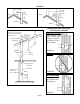

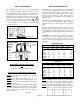

CLEARANCES
If the area where the appliance is to be installed contains
carpeting, tile, or combustible materials, other than wood
flooring, the appliance shall be installed on a metal plate
(stoveboard), a wood panel, or other non-combustible
materials. The use of ceramic or quarry tile is acceptable
and provides an appealing surface that is easily cleaned.
This material is to extend 2 inches from each side and 12
inches from the front. It is advisable to extend this to the
wall behind the appliance.
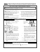
Clearances to combustibles are as follows:
• From jacket to adjacent side walls, 2” on the 20/35, and
6” on the 50/70. Maintain adequate clearance on right
side for accessibility.
• From rear surface vertical vent pipe to rear walls – 6”.
• From rear of unit to rear wall, 13” on 20/35, and 14” on
the 50/70.
• From top of heater to ceiling, 34” on the 20/35, and 31”
on the 50/70.
• From top of heater to any overhanging projections such
as a mantle or window sill is 22” on the 20/35, and 19
inches on the 50/70 models, with a maximum horizontal
extension of 18 inches.
The clearances around the air opening into the combustion
chamber must be maintained, and the burner must be kept
clean.
Do not permit dust or dirt to accumulate here. The other
clearances previously mentioned must be maintained.
There must be adequate room provided and maintained
around the heater for accessibility and for the flow of
combustion and ventilation air.
Projection
Projection
CLEARANCES - VC20, VC35, VCR35
CLEARANCES - VC50 & VC70,
VCR50 & VCR70
Page 7
Projection
Projection
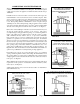
DRAFT DIVERTER
The draft diverter must be installed in the same atmospheric
pressure zone as the combustion air supply for the main burner.
DOOR KNOB
Remove from the inside of the casing door and assemble to
the outside of the door. VC201 and VC202 have finger holes
in the door in lieu of knob.
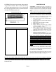
WIRING DIAGRAM
TEMPERATURE
CONTROL
BLOCKED FLUE
SWITCH
PILOT
GENERATOR
18 IN.
45.72 CM
Ceiling
Wall
Floor
34 IN.
86.36 CM
22 IN.
55.88 CM
6 IN.
15.2 CM
13 IN.
33 CM
20/35
Ceiling
Wall
Floor
18 IN.
45.72 CM
6 IN.
15.2 CM
14 IN.
35.6 CM
31 IN.
78.7 CM
19 IN.
48.3 CM
50/70