
- COZY INSTALLATION AND OPERATING INSTRUCTIONS Gas-Fired Vented Room Heater VC201A-H, VC202A-H, VC351A-H, VC352A-H, VC501A-H, VC502A-H, VC701A-H, VC702A-H, VCR351A-H, VCR352A-H, VCR501A-H, VCR502A-H, VCR701A-H, VCR702A-H
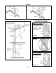
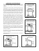


PILOT ADJUSTMENT
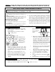
The pilot flame can be observed by opening the pilot lighting
hole cover. The pilot flame should surround the top 3/8 to ½
inch of the thermocouple (see Figure 2). If the flame needs
adjusting, first locate the pilot adjustment screw cap and remove.
Adjustment screw is underneath (see Figure 1). To increase the
flame, turn the pilot adjustment screw counterclockwise .
To decrease the flame, turn the screw clockwise . NOTE:
The pilot is unregulated. If incoming line pressure is more than
7” w.c. Natural Gas or 11” w.c. for L.P. Gas, the pilot flame size
should be decreased.
PILOT FLAME
ADJUST-
MENT
Pilot flame
should
envelop
3/8 to 1/2
inch on the
tip of the
generator.
FIGURE 2
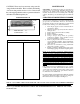
RADIANTS AND GLASS PANELS
FOR ALL VCR MODELS
(See Figure 9 – Replacement Parts Section)
INSTALL GLASS AND RADIANTS AS FOLLOWS:
STEP 1. Remove three screws from under top of opening in
bezel frame assembly.
STEP 2. Pull top of bezel down and lay aside.
STEP 3. Remove glass from bottom pad in shipping carton.
STEP 4. Remove carton containing radiants from cavity of
combustion chamber.
STEP 5. Remove radiants from carton and install by tilting
backwards and lifting at the same time into opening. Place
the radiants on the burner radiants supports. The radiants
must be straight. Never operate heater if any radiant is
tilted to front or rear.
Continued
STEP 6. Install glass panels by inserting top edge into upper
retainer and lower into bottom support, and slide glass into
position. Do not allow a crack between the two glass panels.
Never operate heater with either glass missing or cracked.
STEP 7. Re-install bezel by placing bezel tabs over lower front
and swing bezel into position and secure with three screws.
MAIN BURNER ORIFICE
This appliance was shipped from the factory with an orifice
sized to give the correct gas input using the gas for which the
heater was equipped. There may be local conditions, such as
variation in gas pressure or BTU content of the gas, which
may be cause for a change in the orifice. The gas company
supplying the fuel or the installing contractor should check
the gas input rate.
If the rate exceeds the “BTUH INPUT” on the rating plate by
5%, the orifice should be replaced with a smaller orifice by a
qualified technician to reduce the input to the rating plate
value.
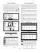
The input rate may need to be adjusted for elevation. See the
following charts to determine the correct orifice size for your
Model Number and elevation. These orifice sizes are based
on a heating value of 1020 for Natural Gas and 2500 for L.P.
Gas.
CAUTION: As elevation increases, derating is necessary for
the safe and proper operation of this heater. Do not increase
the Btu input rate by increasing the orifice size or gas
pressure. Allow for elevation derating when sizing gas heating
equipment.
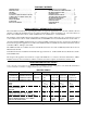
SPECIFIC ELEVATIONS
Model 0 to 2,000- 4,000 - 6,000 - 8,000’
No. 2,000’ 4,000’ 6,000’ 8,000’ 10,000’
VC201 45 47 48 49 50
VC351 35 37 38 40 42
VC501 30 31 31 32 35
VC701 25 27 28 29 30
VCR351 35 37 38 40 42
VCR501 30 31 31 32 35
VCR701 25 27 28 29 30
ORDER KIT #49820 45-1 HIGH ALTITUDE KIT
SPECIFIC ELEVATIONS
Model 0 to 2,000- 4,000 - 6,000 - 8,000’
No. 2,000’ 4,000’ 6,000’ 8,000’ 10,000’
VC202 1.3mm 55 56 56 57
VC352 1.65mm 53 53 54 54
VC502 47 49 49 50 51
VC702 41 42 43 44 46
VCR352 1.65mm 53 53 54 54
VCR502 47 49 49 50 51
VCR702 41 42 43 44 46
ORDER KIT #49820 45-1 HIGH ALTITUDE KIT
NATURAL GAS
L.P. GAS
Page 8
3/8 TO
1/2 INCH
Pilot Adj. Screw
FIGURE 1