
Manual


LOUROE ELECTRONICS, 6955 VALJEAN AVE., VAN NUYS, CA 91406 (818) 994-6498 FAX 994-6458
www.louroe.com / sales@louroe.com
LOUROE ELECTRONICS, 6955 VALJEAN AVE., VAN NUYS, CA 91406 (818) 994-6498 FAX 994-6458
www.louroe.com / sales@louroe.com
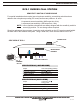
2 Conductor shielded 22 gauge with a
24 gauge drain wire
West Penn 452
or equivalent
To Louroe
Base Station
ALA-4, ALA-8,
DG-12II or DG-25III
1
2
3
4
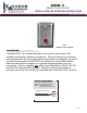
Model DCS-1
PC Board
(Ground) C
(12Vdc Power) A
(Audio Output) B
The PC board of DCS-1 contains a barrier block with four terminals marked 1, 2, 3 and 4.
1 - Ground or common
2 - Jumper (installed by factory). This terminal not used with DCS-1 installation.
3 - Output of oscillator
4 - 12Vdc Power - positive
WIRING CONNECTION TO DCS-1 DURESS CALL STATION
CONNECTION TO MODEL ALA-4 OR ALA-8
Located on rear panel of ALA-4/ALA-8 is a row of terminal blocks marked:
B+ (12Vdc power)
Mic (Audio Output)
Gnd (Ground)
Using recommended cable connect:
Red wire to B+ (12Vdc)
Black wire to Mic (Audio Output)
Bare wire to Gnd (Ground)
CONNECTION TO MODEL DG-12II OR DG-25III ALARMING BASE STATION
Located on rear panel are 12 or 25 sets of 5-pin headers marked A, B, C, SP and G. Connect:
Red wire to pin A
Black wire to pin B
Bare wire to pin C
Pins SP and G are not used with this application
Refer to installation/operation instructions of ALA-4/ALA-8 and
DG-12II/DG-25III for additional information
CONNECTING MODEL DCS-1 TO A LOUROE ALARMING BASE STATION
INSTALLATION INSTRUCTIONS
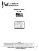
WIRE COLOR CODE OF WEST PENN 452
- 12Vdc
BLACK - Audio Output
- Ground
If using wiring from other manufacturers,
color code may vary.
RED
BARE
BLACK
BARE
LOUROE ELECTRONICS, 6955 VALJEAN AVE., VAN NUYS, CA 91406 (818) 994-6498 FAX 994-6458
www.louroe.com / sales@louroe.com
(page 2 of 3)
LOUROE ELECTRONICS, 6955 VALJEAN AVE., VAN NUYS, CA 91406 (818) 994-6498 FAX 994-6458
www.louroe.com / sales@louroe.com
(page 2 of 3)
dcs-1 1/08