
Manual
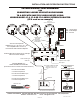


CONNECTION BETWEEN IF-2/IF-4/IF-8 AND DVR (OR OTHER AUDIO RECEIVING DEVICES)
The output side of IF-2/IF-4/IF-8 has two outputs per microphone
1. RCA type output for connection to a DVR, etc. with RCA audio inputs
2. 3.5mm type output for connection to a DVR, IP Network Camera or DVR that has 3.5mm
audio inputs
If the receiving device contains RCA type “audio in” jacks, then connect from Audio Out of IF-2/IF-4/IF-8 to
Audio In of DVR, using the provided RCA connector cables.
If the receiving device contains 3.5mm mono audio inputs, connect 3.5mm mono cable (supplied) between the
output of the IF-2/IF-4/IF-8 and the audio inputs of the DVR, using provided 3.5mm mono
cables.
If the receiving device contains 3.5mm stereo audio inputs, connect one end of the 3.5mm mono cable directly
to the output side of the IF-2/IF-4/IF-8 and use mono to stereo adapter (supplied) for
connecting to DVR’s audio input.
Included with the units are:
2, 4 or 8 RCA to RCA cables
2, 4 or 8 3.5mm mono to mono cables
2, 4 or 8 3.5mm mono to stereo adapters
APPLYING POWER TO THE IF-2/IF-4/IF-8
Included with the IF-2/IF-4/IF-8 is a power supply (120V/12Vdc). Connect the small end of the 90°
female plug into the 12Vdc jack, located on the input side. Then connect the two-prong large end into a
standard 110/120V electrical outlet.
Turn ON/OFF power switch, located behind green power LED to ON position. The green LED will
illuminate, indicating power to the system. The system will now provide audio to the DVR, Soundcard
Module, IP Network Camera, etc.
AUDIO LEVEL ADJUSTMENT
Located on the input side are potentiometers (round, with adjustment arrow) for each microphone. This
is for adjusting the audio gain and to prevent overdriving or underdriving the audio signal.
The adjustment arrows are shipped in the straight-up position. Turn slowly counterclockwise to lower the
gain, and clockwise to increase. This will provide the desired level of audio signal into the Audio
Receiving Device (DVR, Soundcard Module, etc.). A full turn clockwise increases the gain to 10dB. A
full turn counterclockwise will decrease the gain 30dB.
AUDIO TEST SWITCH
The purpose of this switch is to indicate the presence of audio and to assure the user that the IF-2/IF-4
or IF-8 is driving the audio signals into the audio input of receiving device (DVR, IP Network Camera,
Video Server, Soundcard module, etc.)
Located on the audio output side of IF-2/IF-4/IF-8 is a DIP switch labeled Audio Test Switch. To the left
of the switch is a red LED marked Audio Indicator.
For testing:
1) Select a zone that has a microphone connected to the microphone terminal block.
IF-2 utilizes pins 1&2. IF-4 utilizes pins 1, 3, 5, 7. IF-8 utilizes pins 1-8.
2) Push pin to the ON position. The red LED will illuminate, indicating audio is present.
With short bursts of audio, the LED will flicker and with continuous flow of audio LED
illumination is constant.
NOTE: Only one microphone can be tested at a time
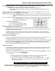
STEREO PLUG
3.5mm Plug
MONO PLUG
two bands
stereo
one
band
LOUROE ELECTRONICS 6955 VALJEAN AVE, VAN NUYS, CA 91406 TEL (818) 994-6498 FAX (818)994-6458
Website: www.louroe.com Email: sales@louroe.com
INSTALLATION AND OPERATING INSTRUCTIONS
IF-2/IF 4/IF 8 in 7/07
PAGE 2 of 4