
Installation Manual

WIRING CONNECTION TO SPEAKER AND MICROPHONE OF AOPSP-PB
Connect the two wires (blue and blue/white) attached to Call Button Switch to the contacts of the
receiving device, using wire nuts and 22 gauge stranded wire. Refer to the receiving device
manufacturers instructions for proper connection.
Page 2 of 4
LOUROE ELECTRONICS® 6955 VALJEAN AVENUE, VAN NUYS, CA 91406 TEL (818) 994-6498 FAX 994-6458
website: www.louroe.com e-mail: sales@louroe.com
(818)
INSTALLATION AND OPERATING INSTRUCTIONS
WIRING CONNECTION TO AOP-530 CALL BUTTON
aop530_540_inst 11/17
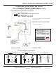
Located on the bottom right side of PC board is a 5-pin terminal
block marked IN, GND, OUT, GND, PWR
IN = Speaker Output
OUT = Audio Output
GND =
PWR
GND = Ground (bare wire)
Ground (-12VDC)
= +12VDC
1) Connect RED wire to terminal marked “IN”
2) Connect BLACK wire to terminal marked “GND” (together with bare wire)
3) Connect BARE wire to terminal marked “GND“
4) Connect WHITE wire to terminal marked “OUT“
WIRING REQUIREMENTS
3 Conductor consisting of:
+
2 Conductor , 20 gauge
with 22 gauge drain
+
1 Conductor , 20 gauge
All in the same jacket
shielded
unshielded
WIRING CONNECTION TO IP CAMERA OR DVR
POWER CONNECTION
Bring the other end of the cable to connector that matches the audio input
and outputs of the receiving devices
1) RED (positive audio) and BARE (ground) are soldered to the audio
connector (RCA, 3.5mm Mono or Stereo plugs). This connector goes
to the Audio output of the receiving device (IP Camera, DVR, etc)
2) WHITE (positive audio) and BLACK (ground) are soldered to the another
audio connector (RCA, 3.5mm Mono or Stereo plugs. This connector
goes to the Audio input of the receiving device (IP Camera, DVR, etc).
The unit has a 2-pin terminal block for power connections marked 12Vdc
1) Connect the positive 12Vdc of the power supply to the terminal marked
PWR
2) Connect the negative or ground of the power supply to terminal marked
GND
WIRING CONNECTION TO AOP-530/540
See connections on the next page