
Installation Manual
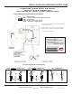

INTERCONNECTION DIAGRAM
CONNECTING LOUROE MODEL AOP 530/540
DIRECTLY TO AN IP CAMERA, DVR,
VIDEO SERVER, ETC. USING 3-COND. SHIELDED CABLE
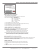
5-PIN TERMINAL BLOCK IDENTIFIER OF AOP-530/540
( ) IN = Speaker Output
( ) GND = Ground (audio), Ground (speaker) (black wire)
( ) OUT = Audio output
( ) GND = 12VDC power supply ground
red
bare/
white
blk
( ) PWR = 12VDC power supply positive
bare/blk
Audio In
Audio In
Audio Out
Audio Out
Bare Wire
Red Wire
RCA CONNECTION
3.5mm CONNECTIONMONO
3.5mm CONNECTIONSTEREO
White Wire
Black Wire
Black Wire
White Wire
Red Wire
Bare Wire
M
O
N
O
M
O
N
O
S
T
E
R
E
O
S
T
E
R
E
O
Audio In
Audio Out
Red Wire
Black Wire
White Wire
Bare Wire
WIRING REQUIREMENTS
3 Conductor consisting of:
+
2 Conductor , 20 gauge
with 22 gauge drain
+
1 Conductor , 20 gauge
All in the same jacket
shielded
unshielded
Page 3 of 4
LOUROE ELECTRONICS® 6955 VALJEAN AVENUE, VAN NUYS, CA 91406 TEL (818) 994-6498 FAX 994-6458
website: www.louroe.com e-mail: sales@louroe.com
(818)
INSTALLATION AND OPERATING INSTRUCTIONS
aop530_540_inst 11/17
AOP 530 ONLY
12 Vdc power is required to connect the AOP-530/540
directly to an IP camera
Positive 12Vdc connects to terminal marked “PWR”
Negative 12Vdc connects to terminal marked “GND”
+12Vdc 1.5A power required