
User's Manual
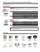

Model LUH-15TX
EXPOSED
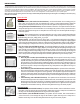
• Open Architecture (with installer-furnished hardware): Use the two threaded 1/4–20 mounting posts on back of horn to mount
horn using 1/4-20 threaded rods or bolts, or custom rigging hardware.
• Ceiling or Wall (with LUH-BRKT bracket): Mount bracket to surface. Use the two threaded 1/4–20 mounting posts on back of horn
to mount the horn to bracket.
RECESSED
Before mounting the horn in recessed applications, be sure to check for obstructions behind the ceiling or wall. For more information,
see the technical paper online at https://www.lowellmfg.com/wp-content/uploads/Checking_above_the_ceiling_before_you_cut.pdf
• Existing Drywall (with SQLK-8L grille and P875X-4 or P875X-6 backbox): Cut hole in ceiling or wall according to instructions on
backbox. Run speaker wire into box and recess-mount box into wall. Mount SQLK-8L grille to horn and attach assembly to backbox.
SURFACE-MOUNT
• Interior Surface (with SQLK-8L grille and CB84 or CB86 backbox): Run speaker wire into backbox and mount to surface. Mount
SQLK-8L grille to horn and attach assembly to backbox.
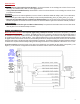
WIRING & SCHEMATICS
Model LUH-15TA & LUH-15TX: Horn ships with pigtail exiting a waterproof connector. The red wire is the positive (+) conductor
and the black wire is the negative (–) conductor. The pigtail has been factory-connected to the 25V/70V/100V input terminals inside of
the termination compartment. A splice can be made to the pigtail, using UL-approved splice connectors, if the splice is made inside a
UL recognized junction box (ex. Lowell LUH-BOX). If a UL-approved junction box is not used, the waterproof tting should be loosened,
the pigtail should be disconnected and removed, the eld wiring should be fed through the waterproof connector, and the termination
should be made directly to the input terminals in the termination compartment. The waterproof tting should then be tightened. Note that
to maintain a UL-required seal at the waterproof tting, the eld wiring used must have a round jacket with a diameter of 0.197” to 0.354”.
For 8-ohm connection, remove the jumper on the upper 8-ohm terminal strip, and terminate the input wiring on the positive (+) and
negative (–) 8-ohm terminals. This bypasses the transformer and selector switch as shown on the schematic below.
3