Pub. 988-0151-271 www.lowrance.
Copyright © 2005 Lowrance Electronics, Inc. All rights reserved. No part of this manual may be copied, reproduced, republished, transmitted or distributed for any purpose, without prior written consent of Lowrance Electronics. Any unauthorized commercial distribution of this manual is strictly prohibited. Lowrance® and GlobalMap 5500C and GlobalMap 4900M are registered trademarks of Lowrance Electronics, Inc. MapCreate, FreedomMaps, IMS and NauticPaths are trademarks of LEI.
Table of Contents Section 1: Read Me First!.......................................................................................1 Capabilities and Specifications: GlobalMap 5500C & GlobalMap 4900M ............................................................................................2 How Lowrance GPS Works..................................................................................4 Introduction to GPS and WAAS...........................................................................
Transfer Custom Maps and GPS Data Files .......................................................53 Custom Maps ..................................................................................................53 GPS Data files.................................................................................................53 Cancel Navigation ..............................................................................................55 Section 4: Advanced GPS Operations......................................
Map Auto Zoom..................................................................................................78 Map Data.............................................................................................................78 Earth Map Detail.............................................................................................79 Pop-up Map Info.............................................................................................79 Draw Map Boundaries ...................................
WARNING! A CAREFUL NAVIGATOR NEVER RELIES ON ONLY ONE METHOD TO OBTAIN POSITION INFORMATION. CAUTION When showing navigation data to a position (waypoint), a GPS unit will show the shortest, most direct path to the waypoint. It provides navigation data to the waypoint regardless of obstructions.
Section 1: Read Me First! How this manual can get you out on the road, fast! Welcome to the exciting world of GPS satellite navigation! We know you're anxious to begin finding your way with this space-age technology, but we have a favor to ask. Before you grab the GlobalMap and begin installing it, please give us a moment or two to explain how our manual can help you get the best performance from your highresolution, high-performance GPS+WAAS chart recorder.
Section 3 contains short, easy-to-scan GPS lessons that follow one another in chronological order. They're all you'll need to know to find your way on the water or in the wilderness quickly. After you've learned the basics (or if you already have some GPS experience), you may want to try out some of the GlobalMap's many advanced navigation features. That brings us to Section 4, Advanced GPS Operations. This section contains the rest of the unit's GPS command functions, organized in alphabetical order.
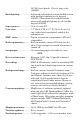
307,200 total pixels; 10-level gray scale (4900M). Backlighting: ................... Advanced cold cathode screen backlit screen with multiple lighting levels; keypad (5500C); Fluorescent cold cathode backlit screen with multiple lighting levels; backlit keypad (4900M). Input power:................... 10 to 15 volts DC. Case size:......................... 7.3" H x 9.6" W x 3.7" D (18.5 x 24.4 x 9.4 cm); sealed and waterproof; suitable for saltwater use. MMC slots: ......................
Audible alarms: ............. Arrival/off-course/anchor. Graphic symbols for waypoints or event marker icons: ................. 42. Routes:............................. 100; up to 100 waypoints per route. Plot Trails: ...................... 10 savable; up to 9,999 points per trail. Zoom range:.................... 37 ranges; 0.05 to 4,000 miles. NOTE: The above memory capacities refer only to the GlobalMap's on-board memory.
to the WAAS satellites in orbit, but more about that in the upcoming segment introducing you to GPS and WAAS.) Your unit listens to signals from as many satellites as it can "see" above the horizon, eliminates the weakest signals, then computes its location in relation to those satellites. Once the GlobalMap figures its latitude and longitude, it plots that position on the moving map shown on the screen. The whole process takes place several times a second! The performance doesn't stop there.
matter where they come from, GPS Data Files must be loaded from the MMC into memory before the GlobalMap can use them.) The other key GPS use for MMCs is storage of special high-detail, custom maps, which you can produce on your computer with our MapCreate software. These MapCreate custom maps contain much greater detail than the basic background map. These Custom Map Files (file format *.lcm) can also be shared between Lowrance GPS or sonar/GPS units and personal computers.
A minimum of three satellites are required to determine a 2D fix. Twenty-four satellites orbit 10,900 nautical miles above the Earth, passing overhead twice daily. A series of ground stations (with precisely surveyed locations) controls the satellites and monitors their exact locations in the sky. Each satellite broadcasts a low-power signal that identifies the satellite and its position above the earth. Three of these satellites are spares, unused until needed.
formance even further with its Wide Area Augmentation System, or WAAS. This GPS add-on will include a time control element that will help airliners fly closer together while avoiding collisions. In addition to carefully spacing airplanes along travel corridors, WAAS will eventually make instrument landings and takeoffs more accurate as it replaces existing aviation navigation systems. Non-aviators can use WAAS signals to make their GPS navigation even more accurate.
around the menus so you can execute different commands. They are represented by symbols like these, which denote the down arrow key, the up arrow, the left arrow and the right arrow: ↓ ↑ ← →. Keyboard The other keys perform a variety of functions. When the text refers to a key to press, the key is shown in bold, sans serif type. For example, the "Enter/Icons" key is shown as ENT and the "Menu" key is shown as MENU.
some of your unit's menus. Most notably, the GlobalMap 5500C has the transparency feature and the GlobalMap 4900M does not.
Section 2: Installation & Accessories Preparations You can install the GPS system in some other order if you prefer, but we recommend this installation sequence: Caution: You should read over this entire installation section before drilling any holes in your vehicle or vessel! 1. Determine the approximate location for the GPS unit, so you can plan how and where to route the cables for the antenna and power. This will help you make sure you have enough cable length for the desired configuration. 2.
You need to select an antenna installation location that has a clear, unobstructed view of the sky. After the module is installed, connect it to the unit. The LGC-2000 can communicate with your GPS unit either directly (using the supplied extension cable) or through a NMEA 2000 network. NOTE See the module’s instruction sheet, publication part number 9880147-981, for complete installation instructions.
the previous image and attach the NMEA 2000 buss adapter cable to the shorter branch of the extension cable's Y-adapter. Connect the NMEA 2000 buss adapter cable's other end to an available network port. To unit LGC-2000 25' Y-adapter extension cable To NMEA 2000 network port LGC-2000 and GPS unit connection to NMEA 2000 buss. You can also attach the antenna to a remote port on the network, and pass position information along the network.
Power Supply wires: red, black and white To unit NMEA-2000 Power wires: red, black and shield Data Cable wires: blue, yellow, orange and shield The Power/Data cable for this unit. Depending on your configuration, you may not use all of these wires. The following segments include instructions for installing all the wires that you will use with this unit. CAUTION: All of the wires in the power/data cable have bare ends for easier installation.
Powering Your Unit (Power Supply cable – red and black wires) The unit works from a 12-volt battery system. For the best results, attach the power cable directly to the battery. You can attach the power cable to an accessory or power buss, however you may have problems with electrical interference. Therefore, it's safer to go ahead and attach the power cable directly to the battery.
To unit NMEA 0183 Data cable (four wires) To power a NMEA-2000 buss, also connect NMEA-2000 Power cable to the boat's battery. Unit power supply cable Optional power off switch for saltwater installations Black wire Red wire with 3 amp fuse White speaker wire NMEA 2000 Power cable Speaker 12 volt battery Black speaker wire Power and optional speaker connections for the GlobalMap 5500C and 4900M GPS units.
larger boat — but still want to hear its alarms. You might install a small speaker at the stern of your boat so you won't miss a dangerous Shallow Alarm while fishing, or put one in your galley so you can hear the GPS Arrival Alarm. You can purchase an external speaker and the wire to connect it at your nearest audio or marine electronics store. You will need to buy marine-grade 18 gauge stranded wire. Buy enough of one color (we suggest white) to run from the unit's Power/Data cable to the speaker.
To do so, attach the adapter cable's manual locking collar connector to the Network port on the back of the GPS unit and attach the other end to an available port on the NMEA 2000 buss, as shown in the following figure. To NMEA 2000 network port To unit's Network socket Lowrance unit direct connection to NMEA 2000 buss. As soon as the unit is connected to the network, it will begin receiving shared information. Please note the buss must be powered to operate.
Blank Network Power/Data 25' Y-adapter extension cable NMEA 0183 Data cable (four wires) 60-ohm terminator NMEA 2000 Power cable Power Supply wires LGC 2000 GPS Module 19
Mounting the Unit: Bracket, In-Dash or Portable You can install the GlobalMap on the top of a dash with the supplied gimbal bracket. It can also be installed in the dash or mounted on a portable power supply. If you use the supplied bracket, you may be interested in the optional R-A-M bracket mounting system. This converts the unit's gimbal bracket to a swivel mount, which can be used on the dash or overhead mounting positions. Installation instructions are supplied with the R-A-M mounting kits.
Cable hole Screw mounting hole Front Install the gimbal bracket. Place the bracket so the arms slope toward the front of your unit. Once a location is determined, use the bracket as a template and mark the mounting holes and the hole for the cables. Drill a 1-inch (25.4 mm) hole in the dash for the power, transducer and antenna cables. Screw the bracket to the mounting surface. 244 [9.58] 37.1 [1.37] 94 [3.61] 185 [7.34] Millimeter [Inch] 56.9 [2.
tenna connector and any accessory cables. Next, pass the power cable's bare-wire end down though the hole from the top. If you wish, you can fill in the hole around the cables with a good marine caulking compound. No matter what type of installation you prefer, be sure to leave enough slack in the cables to allow tilting or swiveling the unit. Attach the unit to the gimbal bracket using the supplied gimbal knobs and washers. Attach the cables and the unit is ready to use.
in your own car or boat, then take it along when riding in a friend's vehicle that's not equipped with GPS. The portable power pack includes a sealed, rechargeable battery. MMC or SDC Memory Card Installation Your unit uses MultiMedia Cards to store information, such as custom maps, waypoints, trails and other GPS data. The unit can also use Secure Digital Cards (SD card or SDC) to store data. The unit can use up to two cards; an MMC and an SDC can be used at the same time.
Slide the drawer back into the unit and twist the retainer clockwise. The MMC is now ready for use. Other Accessories Other accessories include MMC cards, MMC card readers and MapCreate™ 6 custom mapping software for your computer. MMC card readers are available in USB versions. If these accessories are not available from your dealer, see the accessory ordering information on the inside back cover of this manual. MapCreate™ 6 CD-ROM, left; MMC card reader for USB ports, right.
Section 3: Basic GPS Operations This section addresses the unit's most basic GPS operations. The tutorials presented in Sec. 3 follow a chronological order. Sec. 4, Advanced GPS Operations, will discuss other more advanced functions and utilities. Material in Sec. 4 is arranged in alphabetical order. Before you turn on the unit and find where you are, it's a good idea to learn about the different keys, the three Page screens and how they all work together.
1. PWR/LIGHT (Power & Light) – The PWR key turns the unit on and off and activates the backlight. 2. PAGES – Pressing this and the ← → arrow keys (4) switches the unit between the three different page screens. (Satellite Status Page, Navigation Page and Map Page.) Each page represents one of the unit's major operation modes. 3. MENU – Press this key to show the menus and submenus, which allow you to select a command or adjust a feature.
the unit do something. The unit will work fine for these lessons right out of the box with the factory default settings. But, if you want to learn about the various options, see Sec. 5, System Setup and GPS Setup Options. You can access the Main Menu from any of the three Page screens by pressing MENU|MENU. To clear the menu screen and return to the page display, press EXIT. Main Menu. The Main Menu commands and their functions are: Screen command: changes the contrast or brightness of the screen.
Trip Calculator command: shows trip status and statistics. Timers command: controls the up timer, down timer and alarm clock settings. Browse MMC Files command: this allows you to view the installed MMC card and the files it contains. Pages The unit has three Page displays that represent the three major operating modes. They are the Satellite Status Page, the Navigation Page and the Map Page. They are accessed by pressing the PAGES key, then using → or ← to select a Page.
Satellite Status Page from the GlobalMap 4900 (left) indicates unit has not locked on to any satellites and does not have a fix on its position. This view of the GlobalMap 5500 (right) shows satellite lock-on with a 3D position acquired (latitude, longitude and altitude) and WAAS. This screen shows a graphical view of the satellites that are in view. Each satellite is shown on the circular chart relative to your position. The point in the center of the chart is directly overhead.
The navigation screen looks like the one below when you're not navigating to a waypoint or following a route or trail. Your position is shown by an arrow in the center of the screen. Your trail history, or path you've just taken, is depicted by the line extending from the arrow. The arrow pointing down at the top of the compass rose indicates the current track (direction of travel) you are taking.
to the destination. No matter what direction you are steering, the Bearing window shows the compass direction straight to the destination from your location at the moment. Distance shows how far it is to the waypoint you're navigating toward. The Off Course window shows the current cross track error. This shows the distance you are off-course to the side of the desired course line. The course line is an imaginary line drawn from your position when you started navigating to the destination waypoint.
Current track or heading, shown in degrees Trail line Course line Bearing arrow Compass bearing to destination Navigation information displays Waypoint symbol Left cross track error line Cross track error range (off course indicator) Destination name The GlobalMap 4900M navigation page, backtracking a trail while creating a new trail. In the example above, the driver is headed north (a 355º track) toward a waypoint 355º (bearing) away. The cross track error range (white corridor) is 0.
In the first example below, the range is 4,000 miles from the left edge of the map to the right edge of the map. The Zoom In and Zoom Out keys zoom the map to enlarge or reduce its coverage area and the amount of mapping detail shown. There are 37 available map zoom ranges, from 0.05 miles to 4,000 miles. Map Page opening screen (left). Zoomed to 100 miles (center) and zoomed to 15 miles (right). Over Zoomed means you have reached the detail limits in an area covered only by the basic background map.
Background map vs. MapCreate map content The background map includes: low-detail maps of the whole world (containing cities, major lakes, major rivers, political boundaries); and medium-detail maps of the United States. The medium-detail U.S. maps contain: all incorporated cities; shaded metropolitan areas; county boundaries; shaded public lands (such as national forests and parks); some major city streets; Interstate, U.S.
Tip: In some urban areas, businesses are so close to one another that their POI icons crowd each other on the screen. You can reduce screen clutter and make streets and other map features easier to see by simply turning off the display of POIs you're not watching for. (To see how, check the text on Map Detail Category Selection, page 81. It shows how to use the Map Categories Drawn menu to turn individual POI displays off and on.
This allows you to change which map the cursor, keyboard and menus operate on. "Active window" will be displayed at the top of the active window. Resize Window is another extremely handy feature for pages that have two major windows. You can change the horizontal size of the windows to suit your viewing preference. Here's how: 1. From any two-window display, press MENU|↓ to RESIZE WINDOW|ENT. 2. Two flashing arrows appear along the centerline dividing the two windows.
GPS Quick Reference Start outdoors, with a clear view of the open sky. As you practice, try navigating to a location at least a few blocks away. While you're learning, navigation in too small an area will constantly trigger arrival alarms. 1. Connect the unit to electric power and the antenna module. Make sure the MMC is in. (See complete installation details beginning on page 11.) 2. To turn on the GlobalMap, press and release PWR key. 3.
Find Your Current Position Finding your current position is as simple as turning the GlobalMap on. With an unobstructed view of the sky, the unit automatically searches for satellites and calculates its position in approximately one minute or less. If for some reason satellite acquisition takes longer, you may be inside a structure or vehicle or in terrain that is blocking signal reception.
POI pop-up name box Cursor line Distance measured by cursor Selected airport Cursor line The selected airport is 4.25 miles away, to the northwest. Selecting Any Map Item with the Cursor 1. Use the zoom keys and the arrow keys to move around the map and find the item you wish to select. 2. Use the arrow keys and center the cursor cross-hair on the desired object. On most items, a pop-up box will give the name of the selected item.
Category Selection menu (left); list of the nearest restaurants (right). 4. If you wish, you could scroll ↑ or ↓ here to select another restaurant, but for now we will just accept the nearest one. Press ENT. 5. The POI information screen appears. (This is how you can use the GlobalMap as a business phone directory!) If you wanted to navigate there, you could press ENT, since the GO TO command is highlighted. But we just want to see it on the map, so press ↓ to FIND ON MAP|ENT.
Map screen showing Find Waypoint, the result of a restaurant search. NOTE: Search works from mapping and POI data loaded in the GlobalMap. If you do not have a high-detailed custom map (containing POI data) for the area you are searching loaded on the MMC, you may not find anything. Set a Waypoint A waypoint is simply an electronic "address," based on the latitude and longitude of a position on the earth.
Step 1. Step 2. Step 4. Step 3. Sequence for setting a waypoint. Step 1: while traveling, quickly press WPT twice to call up Find Waypoint screen (seen in Step 2) and set a point. Step 3: a message says the waypoint has been saved. Step 4: vehicle continues on its way; number waypoint symbol is visible on map. NOTE: The Quick Save method uses the default waypoint symbol until you edit an existing waypoint and change its symbol. (Edit Waypoint Symbol is described in Sec. 4.
Create Waypoint by Entering a Position 1. Press WPT|→ to SUBCATEGORY column|↓ to NEW|ENT. 2. Press ↓ to ENTERED POSITION|ENT|→ to CREATE|ENT. 3. Press → to LATITUDE|ENT. Enter the latitude by pressing ↑ or ↓ to change the first character, then press → to the next character and repeat until the latitude is correct. Press ENT. 4. Press ↓ to LONGITUDE|ENT. Enter the longitude by pressing ↑ or ↓ to change the first character, then press → to the next character and repeat until the longitude is correct.
Waypoint Course line (dotted) Trail line (solid) Off course range, set at 0.20 mile Destination name GlobalMap 4900M navigation Page, navigating toward waypoint 004 and leaving a trail. Set Man Overboard (MOB) Waypoint One of boating's most terrifying events is having a friend or family member fall overboard. This situation can be deadly on any body of water. It's particularly dangerous at night or if you're out of sight of land.
Navigating to Man Overboard: navigation page (left) and Map Page (right). The victim is astern of the vessel; the GPS shows which direction to steer to for the rescue. The man overboard position is also stored in the waypoint list for future reference. It can be edited the same as any other waypoint. To cancel navigation to MOB, press MENU|MENU|↓ to CANCEL NAVIGATION|ENT|← to YES|ENT. The GlobalMap stops showing navigation information.
Navigate to cursor. In this example, the cursor is positioned on the town of Oologah, Oklahoma. 3. Press MENU|ENT and the GlobalMap will begin navigating to the cursor location. The Map Page will display a dotted line from your current position to the cursor position. The Navigation Page displays a compass rose showing navigation information to your destination. See the following examples. The 30-mile zoom example (left) shows the dotted course line connecting your current position to your destination.
Navigate to a Point of Interest For POIs that are in view on the map, you can easily use the Navigate to Cursor command above. Just use the cursor to select the POI. The other method involves searching for POIs with the Find Waypoint command, launched with the WPT key. (See the searching example earlier in this section, or turn to Sec. 6, Searching, for detailed instructions on POI searches.
Visible symbol Active symbol Sequence for saving a trail and beginning a new one. My Trails command (left). The arrow to the right of Trail 17 (center) indicates the trail is "active" and the check to the left shows the trail is visible on the map. The Edit Trail menu (right) with Active command selected. 3. Press ↓ → to ACTIVE|ENT. This unchecks the Active option. 4. To return to the previous page, press EXIT|EXIT|EXIT|EXIT.
Tip: Another quick way to stop recording one trail and begin a new one is to use the New Trail command: Press MENU|MENU|↓ to MY TRAILS|ENT|ENT. Caution: You also have the option of completely turning off trail recording, under the trail Options command. If, however, the Update Active Trail option is left turned off, it will cancel the automatic trail creation feature. Displaying a Saved Trail The active trail is automatically displayed on the map (the "Visible" option) with the factory default settings.
The other two methods provide a full range of navigation data and work with both the Map Page and Navigation Page. The only difference between them is "navigating a trail" follows a trail forward, while "backtracking" follows a trail in reverse. When hiking at walking speed with a hand-held GPS, we often just use visual back trailing because it is better following each little turn on a foot path.
Figure 1. Figure 2. Figure 3. Figure 4. Navigate a trail menu sequence: Fig. 1, My Trails command. Fig. 2, Trails Menu. Fig. 3, Edit Trail Menu. Fig. 4, Edit Route Menu with Navigate command highlighted for Trail 6. A trail is always converted to a "route" when you navigate the trail. On the Map Page, the trail you are navigating is represented by a dotted line that alternates with a flashing solid line. The Navigation Page will also show the navigated trail as a dotted line.
Present position arrow North Dotted trail line Trail point Navigate trail, map views: driver is northbound heading straight toward trail point 6 (left). northbound driver has reached point 6 (right) and has turned west to follow trail.
NOTE: If you are already located at or near the end of your trail, the arrival alarm will go off as soon as you hit ENT. Just press EXIT to clear the alarm and proceed. 5. Begin moving and let your GlobalMap guide you. 6. When you reach your destination, be sure to cancel your navigation. Press MENU|MENU|↓ to CANCEL NAVIGATION|ENT. The unit asks if you're sure. Press ←|ENT. Transfer Custom Maps and GPS Data Files Custom Maps Custom maps work only from the MMC card or SDC card.
The Transfer My Data submenu asks if you want to save data to the MMC or load data from the MMC into the unit's memory. 2. The Transfer My Data menu includes a message that tells you if a MMC is present or not. If no MMC is present, you must insert a card to activate the Load or Save commands. To transfer data from the GlobalMap to the MMC press ENT (for SAVE.) To transfer data from the MMC to the GlobalMap press → to LOAD|ENT. 3.
selection. Next, press ↓ to LOAD DATA|ENT. The unit will display a completion message when the data transfer is finished. To return to the Page view, press EXIT repeatedly. Figure 1. Figure 2. Figure 3. Figure 4. These figures show the menu sequence for loading a GPS Data File from a MMC into the GlobalMap's memory. Cancel Navigation You can turn off any of the navigation commands after you reach your destination or at any other time by using the Cancel Navigation command.
Notes 56
Section 4: Advanced GPS Operations NOTE There is a slight difference in menu structure between the GlobalMap 5500C and GlobalMap 4900M. The differences are minimal, but some of the screenshots in this manual may not perfectly match some of your unit's menus. Most notably, the GlobalMap 5500C has the transparency feature and the GlobalMap 4900M does not. Find Distance to Another Location 1. While on the Map Page press MENU|↓ to FIND DISTANCE|ENT. 2.
Icons Icons are graphic symbols used to mark some location, personal point of interest or event. They can be placed on the map screen, saved and recalled later for navigation purposes. These are sometimes referred to as event marker icons. The unit has 42 different symbols you can pick from when creating an icon. Icons are similar to waypoints, but they do not store as much information as waypoints do. You can't use a menu to navigate to icons as you can with waypoints.
The Delete icons menus The Delete All Icons command will ask if you are sure. Press ← to YES|ENT. All icons will be deleted from the map. The Delete by Symbol command will launch the Select Symbol menu. Press ← or ↑ or → or ↓ to select the symbol to delete, then press ENT. A message appears saying all icons with the selected symbol have been deleted. The Delete from Map command will prompt you to move the cursor over an icon to select it. After selecting the icon, press ENT and it disappears from the map.
waypoint. The GPS unit allows you to navigate forward or backward through a route. You can even begin navigating in the middle of a route! Create and Save a Route You have the option of creating and editing a route in the unit, or you can make a route on your computer with our MapCreate 6 software. PC-created Routes MapCreate is the easiest method for preparing a route, simply because your PC's larger screen, keyboard and mouse are easier to manipulate.
Edit Route menu (left). Edit Route Waypoints menu (right), with Add From Map command selected. 3. Use the Zoom keys and arrow keys to move the map and cursor until the cursor is centered on the spot where you want your route to begin. (If you are starting at your current position or the current cursor position, you are already at the starting spot.) 4. Set the first route waypoint and press ENT. In this example, we started our route at the intersection of 11th Street and 145th E. Ave.
turn. Fig. 5. Waypoint (4) set at highway exit to frontage road leading to river. Waypoint (5) ends the route at a tree stand in the hunting area. Fig. 6. Press EXIT to save the route and you return to this screen. 5. Move the cursor to the next point in the route, a spot where you need to turn or change direction, and press ENT to set the next waypoint. 6. Repeat step five until the route reaches your destination. 7. To save your route, press EXIT.
2. Press ↓ to route name|ENT|↓ to WAYPOINTS. Use ↓ and ↑ to select a waypoint, then press ENT. Edit Route Waypoints menu. 3. Use ↓ and ↑ to select a command from the Edit Route Waypoints menu and press ENT. Add From Map lets you insert a waypoint in the route by selecting a location with the cursor then pressing ENT. Add Waypoint calls up the Waypoint List so you can insert a waypoint from the list. Remove Waypoint will delete the waypoint from the route.
Navigate a Route in Reverse Here's how you run a route backwards, from the end waypoint to the beginning waypoint. 1. From the NAVIGATION PAGE, press MENU|ENT or from the MAP PAGE, press MENU|MENU|↓ to ROUTE PLANNING|ENT. 2. Press ↓ to select route name|ENT|↓ to NAVIGATE|→ to REVERSE|ENT|← to NAVIGATE|ENT. 3. Upon arrival at your destination, cancel navigation: press MENU|MENU|↓ to CANCEL NAVIGATION|ENT|← to YES|ENT. Figure 1. Figure 2. Figure 3. Figure 4. Navigating along a route: Fig.
Trails Delete a Trail This is the command used to erase or delete a trail: Press MENU|MENU|↓ to MY TRAILS|ENT|↓ to trail name|ENT|→ to DELETE TRAIL|ENT|← to YES|ENT. Tip: You can also delete all trails at once: 1. Press MENU|MENU|↓ to MY TRAILS|ENT. 2. Press → to DELETE ALL|ENT|← to YES|ENT. Edit a Trail Name To edit a trail name: press MENU|MENU|↓ to MY TRAILS|ENT|↓ to trail name|ENT|ENT. Press ↑ or ↓ to change the first character, then press → to the next character and repeat until the name is correct.
then press → to the next character and repeat until the pattern is correct. Press ENT, then EXIT|EXIT|EXIT|EXIT to return to the previous page display. Edit Trail Menu with Pattern option selected (left). Edited trail with dotted line pattern (right). Utilities Utilities are useful tools for traveling or for outdoor activities. Alarm Clock To get to the alarm clock menu: press MENU|MENU|↓ to TIMERS|ENT|↓ to ALARM CLOCK|ENT.
1. Use the arrow keys to select the waypoint with the cursor. 2. Press WPT|↓ to DELETE WAYPOINT|ENT|← to YES|ENT. To return to the previous page and clear the cursor, press EXIT. To delete all waypoints at one time: press MENU|MENU|↓ to SYSTEM SETUP|ENT|↓ to DELETE ALL MY WAYPOINTS|ENT|← to YES|ENT. To return to the previous page, press EXIT|EXIT. Edit a Waypoint Waypoint Name To edit waypoint name: 1. Press WPT|ENT|ENT|ENT|↓ to waypoint name|ENT|↓ to EDIT WAYPOINT|ENT|ENT. 2.
tions and other factors. 1. Press WPT|→ to SUBCATEGORY column|↓ to NEW|ENT. 2. Press ↓ or ↑ to AVERAGE POSITION|ENT|press → to CREATE|ENT. 3. Wait while the unit takes points to average for the position. (The greater the number of points, the greater the accuracy.) When the desired number of points accumulates, press ENT to create and save the waypoint. 4. The Edit Waypoint menu appears. You can simply save the waypoint by pressing EXIT|EXIT or you can edit the waypoint.
Section 5: System & GPS Setup Options Alarms This unit has three GPS alarms. The factory default setting has all the alarms turned on. You can turn the alarms off and on and change their distance settings. You can set an arrival alarm to flash a warning message and sound a tone when you cross a preset distance from a waypoint. For example, if you have the arrival alarm set to 0.1 mile, then the alarm will flash a message when you come within 0.1 mile of the recalled waypoint.
4. When your adjustments are finished, return to the last page displayed by repeatedly pressing EXIT. IMPORTANT ALARM NOTES: Anchor Alarm — The anchor alarm may be triggered even when you're sitting still. This typically happens when using small (less than 0.05 mile) anchor alarm ranges. Arrival Alarm — If you set the arrival alarm's distance to a small number and run a route (see the Navigate Routes segment), this unit may not show navigation data to the next waypoint once you arrive at the first waypoint.
GPS Auto Search on the GlobalMap 5500C Satellite Status Menu. Here's how to put the unit into auto search mode: 1. Press PAGES until you are on the Satellite Status screen. 2. Press MENU|↓ to GPS AUTO SEARCH|ENT|← to YES|ENT. Check MMC Files and Storage Space To check MMC Files: Press MENU|MENU|↓ to BROWSE MMC FILES|ENT. Main Menu (left), MMC File Browser (right). Communications Port Configuration The GlobalMap has two NMEA 0183 version 2.0 compatible communication ports, also known as com ports.
System Setup Menu with Communications Port highlighted (left) and Communications Port menu (right). For assistance in configuring the unit to communicate with another device, consult the factory. Customer service phone numbers are in the back of this manual. Also see the entry below for to Configure NMEA. To set Com Port Configuration: 1. Press MENU|MENU|↓ to SYSTEM SETUP|ENT. 2. Press ↓ to COMMUNICATIONS PORT|ENT. Configure NMEA You can configure the unit to use specific NMEA sentences. 1.
Menus for changing coordinate system. To get to Coordinate System Selection: 1. Press MENU|MENU|↓ to GPS SETUP|ENT. 2. Press ↓ to COORDINATE SYSTEM|ENT. This unit can show a position in degrees (36.14952°); degrees, minutes and thousandths of a minute (36° 28.700'); or degrees, minutes, seconds and tenths of a second (36° 28' 40.9").
To setup Loran TD: NOTE: If the Loran TD conversion is chosen, you must enter the local Loran chain identification for the master and slaves. Do this by selecting "Setup Loran TD" at the bottom of the "Coordinate System" menu and select the ID. Press EXIT to clear this menu. Configure Loran TD menu. Map Fix Map Fix is used with charts or maps. This system asks for a reference position in latitude/longitude, which you take from a marked location on the map.
1. Press MENU|MENU|↓ to GPS SETUP|ENT. 2. Press ↓ to COORDINATE SYSTEM|ENT. 3. Press ↓ to SETUP MAP FIX|ENT. The following screen appears, and MAP SCALE is highlighted. Press ENT and enter the map's scale. This is generally at the bottom of the paper map. It's shown as a ratio, for example 1:24000. Press EXIT and the unit returns to the Configure Map Fix screen. Configure a map fix so the GlobalMap 4900M can find your position on a printed chart or topographical map.
To change the information displayed in a data box: On the Page display you wish to change, press MENU|↓ to CUSTOMA data box name flashes, indicating it is selected. Press ENT to change the box or hit ↑, ↓, → or ← to select another box, then press ENT. You'll see a list of categories with "+" or "–" symbols next to each category. A category with a "+" is expandable, meaning its contents are hidden. IZE|ENT. Customize Menu, with the GPS Data category expanded.
setting the track and speed in the dialog boxes provided on the simulator menu screen. To get to the GPS Simulator: 1. Press MENU|MENU|↓ to GPS SETUP|ENT. 2. Press ↓ to GPS SIMULATOR|ENT. The GPS Simulator Menu appears. The GPS Setup Menu (left); GPS Simulator menus for the GlobalMap 5500C (center) and the GlobalMap 4900M (right). Make the desired settings, then turn the simulator on by highlighting the GPS SIMULATOR ON box and pressing ENT key. Press EXIT|EXIT|EXIT to clear this menu.
4. Press EXIT to turn off the steering and speed boxes. The unit will now automatically "steer" along the trail or route. When you arrive at your "destination," cancel navigation as you normally do. Tip: You can pick any spot on the map to begin your simulation session by using the Initialize GPS command. This makes your unit think it's located at the position you select. See the following entry. Initialize GPS This command is handy when you are practicing in simulator mode.
map. This menu lets you select Navionics Maps. For instructions, see the Navionics Charts entry in this section. To get to Map Data: From the Map Page, press MENU|↓ to MAP DATA|ENT. Map Menu (left) and Map Data Menu (right). Earth Map Detail From the Map Page, press MENU|↓ to MAP DATA|ENT. Press ENT to check to select the level of map detail you prefer. Use ↑ ↓ to choose off, low, medium or high, then press EXIT to the page display. Pop-up Map Info From the Map Page, press MENU|↓ to MAP DATA|ENT.
check boxes — Show Time and Show Distance — which allow you to turn on or off the time and/or distance settings. To set trackline extension: From the Map Page, press MENU|↓ to MAP DATA|ENT. Press ↓ to TRACKLINE EXTENSION|ENT. Use ↑ ↓ to select the desired distance setting and press ENT. Presentation Mode From the Map Page, press MENU|↓ to MAP DATA|ENT. Press ↓ and → to PRESENTATION MODE|ENT. Use ↑ ↓ to choose the desired depth and press ENT.
lighted, press ENT to check it (turn on) and uncheck it (turn off.) After the option is set, press EXIT|EXIT to return to the page display. Map Datum Selection Maps and charts are based on a survey of the area that's covered by the map or chart. These surveys are called "Datums." Maps that are created using different datums will show the same latitude/longitude in slightly different locations. All datums are named. The GPS system is based on the WGS-84 datum, which covers the entire world.
Map menu (left) and Map Categories Drawn menu (right). Map Orientation By default, this receiver shows the map with north always at the top of the screen. This is the way most maps and charts are printed on paper. In Track Up mode, map shows "N" and arrow to indicate north. Map orientation shown in north up (left) and track up (right). This is fine if you're always traveling due north.
To change map orientation: from the Map Page, press MENU|↓ to MAP ORIENTATION|ENT. Use ↑ or ↓ to select the desired mode, then press ENT. Press EXIT|EXIT to return to the page display. Map Menu (left) and Map Orientation menu with the North Up map orientation option selected (right). Navionics Charts Your GlobalMap can display Navionics electronic charts on MMCs. They work just like a MapCreate custom map on an MMC. Entrance to Chesapeake Bay in a MapCreate 6 custom map, 15-mile zoom (left).
These figures show the menu sequence (from left to right) for selecting a Navionics chart for the South Chesapeake Bay area. 3. To turn off a Navionics chart: from the Map Page, press MENU|↓ to MAP DATA|ENT|→ to MAP CHOICE|ENT. Use ↑ or ↓ to select LOWRANCE, then press ENT|EXIT|EXIT. Port Information Navionics charts contain Port Services information, represented by anchor icons on the map display. An example is displayed in the following figure. To view Port Services information: 1.
Port Services icons Pop-up name box Cursor lines Navionics chart showing Port Services icon selected by cursor. 3. To scroll through the Service Categories window, press ENT then use ↑ or ↓ to see the types of services available. As you highlight a different category, the list in the lower window changes. To return to the Map Page, press EXIT|EXIT. 4. The General Services category includes a long list of items in the Detailed Services window.
you can select the boxed "C" icon and it becomes an animated arrow with a pop-up name box. An example is displayed in the following figure. To view Tidal Current information: 1. Use the arrow keys to move the cursor over a Tidal Current Station icon. When selected, a pop-up name box appears. 2. Press WPT to display the Tidal Current Information screen. Navionics chart showing Tidal Current Station icon selected by cursor.
Slack water, the period of little or no current, is represented by the Slack Water Line (SWL). The flood appears above the SWL and the ebb appears below the SWL. You can look up tidal current data for other dates by changing the month, day and year selection boxes. To select another date: 1. Use → and ← to highlight month, day or year, then press ENT. 2. Use ↑ and ↓ to select the desired month, day or year, then press ENT. To clear the information screen, press EXIT.
Tide Information screen. The Tide Information screen displays daily tidal data for this station at the present time. The graph at the top of the screen is an approximate view of the tidal range pattern for the day, from midnight (MN), to noon (NN) to midnight (MN). The dotted line across the graph is the Mean Lower Low Water line (MLLW). The height scale on the top right side of the graph changes, based upon the maximum range of the tide for that day.
NOTE The Customize command and the Overlay Data command both use the same information categories. The difference between the two commands is that Customize changes only the digital data boxes on a screen, and Overlay Data changes only the information floating on the screen without a box. See Customize Page Displays, on page 75 for information on customizing data boxes. Overlay Data highlighted on GPS menu (left). The Data Viewer menu with the Navigation category expanded.
From Overlay Data Shown menu (left) press ENT to see Data Viewer (center). Select a category and press ENT. Bearing, Closing Speed and Off Course have been selected from the Navigation category. To remove overlaid data: 1. While on the Page that shows the item or items you want to remove, press MENU|↓ to OVERLAY DATA|ENT. 2. You'll see a list of the overlay data currently displayed. Select the item you want to remove from your display and press ENT|ENT to remove the data.
3. The data begins to flash on your screen. Use any combination of →, ←, ↑ and ↓ to move the data to a new location on the screen. 4. When satisfied, press EXIT|EXIT. To resize overlaid data: press MENU|↓ to OVERLAY DATA|ENT. This will bring up the Overlay Data Shown menu with a list of the current overlay data. Use → ← to toggle the size of the data between small, medium, large and enormous. When you are satisfied with the data size, press EXIT.
The GlobalMap 5500C Gauge Setup menu (left) with the GlobalMap 4900M Analog setup menu (right). There are four primary setup options in the analog menu: Themes, Tick Marks, Thresholds and Text. When working in the gauge setup menu, use ↓ ↑ and → ← to highlight the desired option, then press ENT. Pressing EXIT will take you back to the previous screen. NOTE You can make gauges transparent from all the setup menus except Text Setup.
With a single gauge displayed (left), the Sec. Data button is not active. After choosing a dual-gauge setting, the Sec. Data button is active. Choosing the Sec. Data button will take you to the same Data Viewer screen (right) as Customize Page and Overlay Data commands. The Secondary Data or Sec. Data button is only active when you have a dual-gauge setting selected for display. It allows you to choose what information you want displayed in secondary gauge.
decide to start the gauge at 0, 5 or 10 and top it out at 85, 90 or 100. Minimum or Maximum Tick controls how many tick marks will be displayed on the gauge. If you set the minimum tick to 1 and the max tick to 10, there will be 10 tick marks between 0 and 10, 10 and 20 and so on. In the case of a speedometer, that's one tick for one mile per hour. If you change the minimum tick to 2 and leave the maximum tick at 10, you'll have one tick for every two miles per hour.
The GlobalMap 5500C display with a transparent track gauge (left) and the GlobalMap 4900M display with track and speed gauges (right). Pop-up Help Help is available for virtually all of the menus on this unit. By highlighting a menu item and leaving it highlighted for a few seconds, a "pop-up" message appears that describes the function of the menu item. This feature is on by default. To set up Popup Help: Press MENU|MENU|↓ to SYSTEM SETUP|ENT|↓ to POPUP HELP.
NOTE: Reset Options does not erase waypoints, routes, icons or plot trails. Reset Options command (left) and the Reset Options menu (right). Screen Contrast and Brightness To access the Screen menu, press MENU|MENU|ENT. Once in the Screen menu: To adjust the display's contrast: The CONTRAST slider bar is already selected. Press → or ← to move the bar. The left end of the scale is minimum contrast. The right end is maximum contrast. Screen Command (left); Screen Menu with Contrast bar selected (right).
Display Mode menu. Set Language This unit's menus are available in 10 languages: English, French, German, Spanish, Italian, Danish, Swedish, Russian, Dutch and Finnish. To select a different language: 1. Press MENU|MENU|↓ to SYSTEM SETUP|ENT. 2. Press ↓ to SET LANGUAGE|ENT. 3. Use ↓ or ↑ to select a different language and press ENT. All menus now appear in the language you selected. Set Local Time Using the correct local time setting is handy when estimating local arrival time while navigating.
Time Setting menus for the GlobalMap 5500C (left) and the GlobalMap 4900M (right). To Set Time Format: Press ↓ to the Time Format window. Just highlight the option you prefer — 12 or 24 hour — and press ENT. To Set Date Format: Press ↓ and → to modify the Date Format. There are three options: Month/Day/Year, Day/Month/Year and Year/Month/Day. Use ↑ or ↓ to select the format you prefer, then press ENT. The last field in the GlobalMap 4900M menu is CONFIG DST.
Software Version Information From time to time, Lowrance updates the operating system software in some of its products. These software upgrades are usually offered to customers as free downloads from our web site, www.lowrance.com. These upgrades make the unit perform better or introduce a new feature or function. You can find out what software version is running in your GlobalMap by using the Software Information command. Software Information command (left).
option is set, press EXIT|EXIT to return to the page display. To set Alarm Volume: Press ↓ to VOLUME. Press → or ← to move the bar. The left end of the scale is low volume; the right end is high volume. After the option is set, press EXIT|EXIT to return to the page display. To set Alarm Style: Press ↓ to ALARM STYLE|ENT. Press ↑ or ↓ to change the style, then press ENT. After the option is set, press EXIT|EXIT to return to the page display.
Update Trail Option This menu lets you change the way trail updates occur. WARNING: If you uncheck the Update Trail option, automatic trail creation and recording will be turned off. You must turn it back on to record trails. The default setting is on. From the Trails Menu, press → to OPTIONS|ENT. With UPDATE ACTIVE TRAIL highlighted, press ENT to check it (turn on) and uncheck it (turn off). Update Trail Criteria (Auto, Time, Distance) The options are automatic, time, or distance.
Specific Trail Options Delete Trail To delete a specific trail: From the Trails Menu, press ↓ to Trail Name|ENT. The Edit Trail menu appears as seen in the following figure. Press → to DELETE TRAIL|ENT|← to YES|ENT. Edit Trail menu. New Trail To manually start a new trail, in the Trails Menu, make sure NEW TRAIL is highlighted and press ENT|EXIT.
Main Menu with Transparency command selected. To adjust Menu Transparency level: Press MENU|MENU|↓ to TRANSPARENCY |ENT. The TRANSPARENCY slider bar appears. Press ↑ or ↓ to move the bar. The lower end of the scale makes the menus opaque. The upper end is maximum transparency. Units of Measure This menu sets the speed and distance (statute or nautical miles, meters), depth (feet, fathoms, or meters), temperature (degrees Fahrenheit or Celsius) and heading (true or magnetic) units.
To set Speed/Distance Unit of Measure: Press ↑ or ↓ to change the Speed/Distance unit, then press ENT. After the option is set, press EXIT|EXIT|EXIT to return to the page display. To set Heading: Press ↑ or ↓ to select the heading type, then press ENT. After the option is set, press EXIT|EXIT|EXIT to return to the page display.
Section 6: Searching NOTE: The background map loaded in your unit lets you search for U.S. Interstate Highway exits and exit services, as well as some land features, including cities and lakes. For a full set of searchable land features, including landmarks, streets, addresses and Points of Interest, you must load your own high-detail custom map produced with our MapCreate 6 software. For a complete description of what detail is found in the background map and custom MapCreate maps, see page 34.
Find Address Menu. 3. To enter an address number, press ↑ or ↓ to change the first number, then press → to move the cursor to the next number and repeat until the number is correct, then press ENT. 4. To enter a street name, press ↓ to STREET|ENT. There are two options: A. You can spell out the name in the top selection box. Press ↑ or ↓ to change the first letter, then press → to move the cursor to the next letter and repeat until the name is correct, then press ENT|ENT. B.
NOTE: We recommend you do not enter a city name unless the list is too large when searching without one. The GlobalMap can actually search quicker without a city. Find city field (left); Search in particular city only option (center) and Find City by name (right). 6. When the necessary search fields are filled in, press ↓ to FIND ADYour unit asks you to wait while it searches for the address. If an address is not in the database, a message appears saying the address could not be found. DRESS|ENT. 7.
tion window. With the address location selected by the cursor on the map, press WPT. The POI's Waypoint Information window appears, with the Go To Waypoint command highlighted. If you want to navigate to the POI address, just press ENT|EXIT. Map Page showing location of the address on the map, highlighted by the cursor (left). The Address is a business in the POI database (center), so you can display the POI information window, then navigate to it.
Find Highway Exits command (left) and Find Exit menu (right). 2. First, select a highway name by pressing ENT, which calls up the Find By Name menu. There are two highway search options: A. You can spell out the highway name in the top selection box. Press ↑ or ↓ to change the first letter, then press → to move the cursor to the next letter and repeat until the name is correct, then press ENT|ENT. B.
Find Exit menu, with an exit selected in the Exit List. 4. In the Exit Information screen you have two choices. A. Press ENT to navigate or "Go To" the exit. B. Press →|ENT to find exit on the map. Go To Exit option (left) and Find On Map option (right). Tip: You can also look up some additional information on the Exit Services located near this exit. Press ↓ to SERVICES, then press ↓ or ↑ to select Service Name|ENT. Exit Information screen (left); general location and amenities information (right).
Find Map Places or Points of Interest (POI) 1. Press WPT, then use ↓ or ↑ to select a map place or POI category, then press ENT. (To narrow your search, press → then press ↓ or ↑ to select a subcategory before pressing ENT.) You will be given two options; Search By Name or By Nearest. Find Waypoint menu with Lodging POI category selected (left) and with the RV Parks subcategory selected (right). 2. Search by nearest POI. Press ↓|ENT.
Find by Name option (left) and Find by Name menu (right). 4. When the POI's Waypoint Information screen is displayed, you can choose to "Go To" the POI waypoint by pressing ENT or find it on the map by pressing →|ENT. Go To Waypoint POI option (left) and Find on Map POI option (right). Find Streets or Intersections Find a Street 1. From the Map Page, press MENU|↓ to FIND STREETS|ENT and the Find Streets Menu appears.
You can spell out the street in the top selection box. Press ↑ or ↓ to change the first letter, then press → to move the cursor to the next letter. Repeat until the name is correct, then press ENT|ENT. B. Or you can jump down to the lower box and pick a street from the selection list. Press ENT, then press ↓ or ↑ to select a street from the list and press ENT. Find Street By Name menu. Spell out name in the top box, or select from the list in the lower box. 3.
Map Page showing results of a street search. The cursor points to the located street. If you want to navigate to the found street at the cursor location, just press MENU|ENT|EXIT. Find an Intersection You must enter one street in the First Street dialog box and enter the next street in the Second Street dialog box. 1. From the Map Page, press MENU|↓ to FIND STREETS|ENT and the Find Streets Menu appears. 2. You must fill in a street name in the First Street dialog box.
second street. You could now use similar techniques to select a city or Zip code, but your search will probably be faster if you leave those boxes blank. You can specify a city and/or Zip code later to narrow the search, if the resulting list is too long. GlobalMap 5500C (left) and GlobalMap 4900M (center) Find Streets menus with Find Intersection selected; Intersections found list (right). 6. To search for the intersection of the two streets, press ↓ to FIND INTERSECTION|ENT.
If you want to navigate to the found intersection, just press MENU|ENT|EXIT. Find Waypoints 1. Press WPT|ENT. 2. If searching for the waypoint By Name, press ENT. If searching for the Nearest waypoint, press ↓ to NEAREST|ENT. (To search by name, jump to step 5 below.) Find Waypoint menu (left), Find By Nearest command (center) and Find by Name command (right). 3. If you're looking for nearest waypoint, the GlobalMap says it is calculating, then a list of waypoints appears.
Waypoint Information screens with the Go To Waypoint command selected (left) and the Find on Map command selected (right). To clear these menus and return to the previous page, press EXIT repeatedly. 5. If you're looking by name, there are two options: A. You can spell out the name in the top selection box. Press ↑ or ↓ to change the first letter, then press → to move the cursor to the next letter and repeat until the name is correct, then press ENT|ENT. B.
Notes 118
Section 7: Supplemental Material Datums Used by This Unit WGS 1984 Default Zaire, Zambia and Zimbabwe Adindan Mean for Ethiopia, Sudan Arc 1950 - Botswana Adindan Burkina Faso Arc 1950 - Lesotho Arc 1950 - Burundi Arc 1950 - Malawi Adindan Cameroon Adindan Ethiopia Arc 1950 - Swaziland Adindan Mali Arc 1950 - Zimbabwe Adindan Senegal Arc 1960 - Mean for Kenya, Tanzania Adindan Sudan Ascension Island 1958 - Ascension Island Ain el Abd 1970 Bahrain Ain el Abd 1970 Saudi Arabia Anna 1 Astro 1965
Chua Astro Paraguay Corrego Alegre Brazil Dabola Guinea Djakarta (Batavia) Indonesia (Sumatra) DOS 1968 New Georgia Islands (Gizo Island) Easter Island 1967 Easter Island European 1950 Mean for Austria, Belgium, Denmark, Finland, France, West Germany, Gibraltar, Greece, Italy, Luxembourg, Netherlands, Norway, Portugal, Spain, Sweden, Switzerland European 1950 Mean for Austria, Denmark, France, West Germany, Netherlands, Switzerland European 1950 Mean for Iraq, Israel, Jordan, Lebanon, Kuwait, Saudi Arabia,
Naparima BWI Trinidad & Tobago North American 1927 Mean for Antigua, Barbados, Barbuda, Caicos Islands, Cuba, Dominican Republic, Grand Cayman, Jamaica, Turks Islands North American 1927 Mean for Belize, Costa Rica, El Salvador, Guatemala, Honduras, Nicaragua North American 1927 Mean for Canada North American 1927 Mean for CONUS (Continental United States) North American 1927 Mean for CONUS (East of Mississippi River) including Louisiana, Missouri, Minnesota North American 1927 Mean for CONUS (West of Missi
South American 1969 Chile Tokyo Mean for Japan, Korea, Okinawa South American 1969 Colombia Tokyo Japan South American 1969 Ecuador Tokyo Korea South American 1969 Ecuador (Baltra, Galapagos) Tokyo South American 1969 Guyana Tristan Astro 1968 Tristan da Cunha South American 1969 Paraguay South American 1969 Peru Viti Levu 1916 Fiji (Viti Levu Island) South American 1969 Trinidad & Tobago Eniwetok 1960 Point 58 Sweden Santo (DOS) 1965 Espirito Santo Island Sao Braz Azores (Sao Miguel, Santa Ma
FCC Compliance This device complies with Part 15 of the U.S. Federal Communications Commission (FCC) Rules. Operation is subject to the following two conditions: (1) this device may not cause harmful interference, and (2) this device must accept any interference received, including interference that may cause undesired operation. Changes or modifications not expressly approved by the manufacturer could void the user's authority to operate the equipment.
LOWRANCE DATABASES LICENSE AGREEMENT THIS IS A LEGAL AGREEMENT BETWEEN THE END-USER WHO FIRST PURCHASES THIS PRODUCT AS A CONSUMER ITEM FOR PERSONAL, FAMILY, OR HOUSEHOLD USE ("YOU") AND LOWRANCE ELECTRONICS, INC., THE MANUFACTURER OF THIS PRODUCT ("WE", "OUR", OR "US"). USING THE PRODUCT ACCOMPANIED BY THIS LICENSE AGREEMENT CONSTITUTES ACCEPTANCE OF THESE TERMS AND CONDITIONS. IF YOU DO NOT ACCEPT ALL TERMS AND CONDITIONS, PROMPTLY RETURN THE PRODUCT WITHIN 30 DAYS OF PURCHASE.
DATABASES LIMITED WARRANTY "We", "our", or "us" refers to Lowrance Electronics, Inc., the manufacturer of this product. "You" or "your" refers to the first person who purchases the product as a consumer item for personal, family, or household use. The Databases Limited Warranty applies to the one or more databases that your product may contain. We refer to each of these as a "Database" or together as the "Databases.
Notes 126
LOWRANCE ELECTRONICS FULL ONE-YEAR WARRANTY "We," "our," or "us" refers to LOWRANCE ELECTRONICS, INC., the manufacturer of this product. "You" or "your" refers to the first person who purchases this product as a consumer item for personal, family or household use. We warrant this product against defects or malfunctions in materials and workmanship, and against failure to conform to this product's written specifications, all for one (1) year from the date of original purchase by you.
How to Obtain Service… …in the USA: We back your investment in quality products with quick, expert service and genuine Lowrance parts. If you're in the United States and you have technical, return or repair questions, please contact the Factory Customer Service Department. Before any product can be returned, you must call customer service to determine if a return is necessary. Many times, customer service can resolve your problem over the phone without sending your product to the factory.
Accessory Ordering Information for all countries To order Lowrance GPS accessories, please contact: 1) Your local marine dealer or consumer electronics store. Most quality dealers that handle marine electronic equipment or other consumer electronics should be able to assist you with these items. To locate a Lowrance dealer near you, visit our web site, www.lowrance.com and look for the Dealer Locator. Or, you can consult your telephone directory for listings. 2) U.S. customers: LEI Extras Inc.
Visit our web site: Lowrance Pub. 988-0151-271 Printed in USA 012105 © Copyright 2005 All Rights Reserved Lowrance Electronics, Inc.