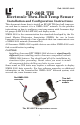
Pub. 988-0154-442 EP-80R TH Electronic Thru-Hull Temp Sensor Installation and Configuration Instructions This document shows how to install an EP-80R TH thru-hull temp sensor and how to connect it to a NMEA 2000® network. It also provides instructions on how to configure your temp sensor with Lowrance digital gauges (LMF-200 & LMF-400) and display units. NMEA 2000 is the communication bus standard developed by the National Marine Electronics Association (NMEA) for use in boats.
Some sonar or GPS units may require a software upgrade to display NMEA 2000 data correctly. For free software upgrades or additional information on the LowranceNet NMEA 2000® network system, visit our web site, www.lowrance.com. The EP-80R TH consists of the temp sensor module, a red cable connector and the smart module, which converts analog temperature data to NMEA 2000 data format.
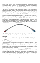
LowranceNET Node Kit for a NMEA 2000 network. Includes a 2-foot extension cable, T connector and two 120-ohm terminators. Recommended Tools and supplies Recommended tools for this job include: drill, 1/8" (3 mm) drill bit for pilot hole, 1-1/16 (27 mm) hole saw with a blade type appropriate for the composition of your transom. Required supplies for this job include: high quality, marine grade aboveor below-waterline sealant/adhesive compound.
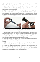
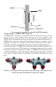
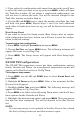
Afterwards, clean the area around the hole with detergent or alcohol. This will establish a good surface for the adhesive. 5. Using a high quality, marine-grade above- or below-waterline sealant/adhesive compound, apply a 1/8" (3 mm) bead of sealant around the lip of the EP-80R TH housing. 6. Make sure the nut has been removed from the sensor module, then from the outside of the transom, pass the EP-80R TH cable through the hole and push the housing with sealant into it.
sealant sealant nut outer hull Inner hull Cross section of transom showing EP-80R TH installed. Connecting to a NMEA 2000 Network A NMEA 2000 network is a communications link between two or more devices that transfer NMEA 2000 information. LowranceNET is the NMEA 2000 networking system developed by Lowrance Electronics. A NMEA 2000 network functions like the phone wiring in a house.
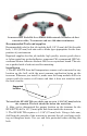
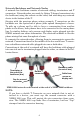
Network Backbone and Network Nodes A network bus backbone consists of network cabling, terminators and T connectors. Network nodes are made by fitting T-shaped connectors into the backbone (using the sockets on the sides) and attaching any network device to the bottom of the T. Staying with the previous phone wiring example, T connectors on the backbone are the equivalent of phone jacks spread throughout a house.
All T connectors on your network probably will be connected to a device. If you want to add another node to a working network, add another T connector. T connectors may be purchased from LEI (ordering information appears on the back page of this booklet). If you are adding a Lowrance or LEI NMEA 2000 sensor, it will come with a T connector. Adding a Network Node You can add a node to any existing connection, anywhere along the network backbone.
Notes 8
LMF-200: EP-80R TH Temp Configuration This section will show you how to use the LMF-200 Multi-function gauge to configure your EP-80R TH Temperature Sensor. NOTE: You will notice the LMF-200 does not have an Exit key. Menus will time out after a preset amount of time (3, 5, 10 or 15 seconds). The default setting is 5 seconds. Refer to your LMF-200 instruction manual for more information on the Timeout feature.
3. If you selected a configuration with more than one tank you will have to select the tank you want to set up and press MENU, which will open the Tank Size window. (If you choose a single-tank configuration, you will not have to choose the tank. You will be directed straight to the Tank Size window covered in Step 4.) 4. Use the UP and DOWN keys to input the number of gallons the tank will hold and press MENU. Repeat steps 3 and 4 for each additional tank.
To unconfigure a temp sensor: 1. Press MENU, use the UP and DOWN keys to select SYSTEM SETUP and press MENU. 2. Highlight B. DEVICES and press MENU, which will open the Bus Devices list. 3. Select a temp sensor from the Bus Devices list and press MENU. The Configuration Options menu will appear with two choices: Unconfig (Unconfigure) and Reconfig (Reconfigure). 4. Select UNCONFIG and press MENU. The following message will appear: Hit Menu to Unset Device Name. 5. Press MENU to unconfigure the sensor.
7. Select RECONFIG and press MENU to open the Selecting Temp menu. Highlight WATER and press MENU. You will be directed to the Bus Devices list. 8. Highlight UNCFG TEMP and press MENU. The following message will appear: Hit Menu to Cfg Temp Sns. 9. Press MENU to be taken to the Selecting Temp menu. Choose OUTSIDE and press MENU. You will be directed to the Bus Devices list, where the two sensors will be listed with their new configuration names. If desired configuration name available: 1.
Customizing Pages The customizing pages feature allows you to choose what data will be displayed and how it will be displayed on select pages. You can customize the Gauge, Single Digital and Dual Digital pages with temp sensor data. To customize Gauge page: 1. After the Gauge page has been added to the page screen rotation, use the UP and DOWN keys to display it on the screen. 2. Press MENU, select CUSTOMIZE and press MENU. 3. Highlight TEMP and press MENU.
Notes 14
LMF-400: EP-80R TH Temp Configuration This section will show you how to use the LMF-400 Multi-function gauge to configure your EP-80R TH Temperature Sensor. LMF-400 Multi-function Digital gauge. Boat Setup If this is the first time you have turned on your LMF-400, you will have to complete Boat Setup before you will be able to configure your temp sensor. If you have already completed Boat Setup, skip ahead to the segment covering EP-80R TH Configuration. To execute Boat Setup: 1.
5. After all tanks on your vessel have been set up, press EXIT repeatedly to return to the main display. Boat Setup Reset If you want to access the Setup screen (Boat Setup) after an enginetank configuration has been chosen you will have to reset the configuration to default settings. To reset engine-tank configuration: 1. Press MENU, highlight SYSTEM SETUP and press ENTER. 2. Choose ENG/TANK CFG and press ENTER twice. The following message will appear: Press ENTER to reset Eng/Tnk Cfg. 3. Press MENU.
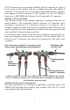
3. Choose the desired temp sensor and press ENTER. Select UNCONFIGURE from the temp configuration menu and press ENTER. The following message will appear: Press Menu to UnConfig Device Name. 4. Press ENTER to unconfigure the sensor and be directed to the Bus Devices list where the temp now will be listed as UnCfg Temp. Bus Devices highlighted in the System Setup menu (left). Searching Bus Devices window (center) with Bus Devices list (right).
configuration menu. Select RECONFIGURE and press ENTER. That will direct you to the Temp Selection menu, which will have three options: Water, Outside and Inside. 6. Select OUTSIDE and press ENTER. You will be taken back to the Bus Devices list. The temp you just reconfigured (formerly water temp) will now be displayed as Outside Temp. 7.
To add a page to the display: 1. Press MENU, use the UP and DOWN keys to select PAGES and press ENTER. A menu will pop up with four options: Add Page, Remove Page, Page Scrolling and Pop-Ups Setup. 2. Select ADD PAGE and press ENTER. 3. Highlight (Single Analog, Dual Analog, Quad Analog, Single Digital, Dual Digital or Quad Digital) and press ENTER. The following message will appear: Press Enter to add the selected page. 4.
5. Highlight TEMPERATURE and press ENTER. The Select Temp menu will appear with three temp types: Water Temp, Outside Temp and Inside Temp. 6. Select the desired temp type and press ENTER. You will be directed to the Position menu. Repeat steps 4 and 5 to customize the other position, or press EXIT twice to return to the main display. To customize Quad Analog page: 1. Make sure the Quad Analog page has been added to the page screen rotation. 2.
4. Select TEMPERATURE and press ENTER. The Select Temp menu will appear with three temp types: Water Temp, Outside Temp and Inside Temp. 5. Select the desired temp type and press ENTER. You will be directed to the Position menu. Repeat steps 3 through 5 to customize the other position, or press EXIT twice to return to the main display. To customize Quad Digital page: 1. After the Quad Digital page has been added to the page screen rotation, use the ENTER and EXIT keys to display it on the main screen. 2.
Notes 22
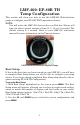
Display Unit: EP-80R TH Temp Configuration All NMEA 2000 capable Lowrance sonar and sonar/GPS combo display units can be used to configure your EP-80R TH thru-hull temp sensor on a NMEA 2000 network. The LMS-525cDF is one of many Lowrance display units that may be used to configure an EP-80R TH thru-hull temp sensor. NMEA 2000 Menu/Networking Menu Your unit may have a NMEA 2000 menu or a Networking menu, depending on the software version installed in your unit.
Bus Setup highlighted on the NMEA 2000 menu (left). Bus Setup selected on Networking menu (right). EP-80R TH Temp Sensor Configuration The Temp Type function will be used when configuring your temp sensor through a display unit. You will select a configuration name for the temp from the Temp Type menu. You can also change the Device Name for your temp sensor.
4. Press ENTER. Use the arrow keys to input the desired name for the temp sensor and press ENTER. Press EXIT repeatedly to return to the main display. To reset device name to default setting: 1. Press MENU twice, select NMEA 2000 or NETWORKING and press ENTER. A menu will appear with five options: Bus Setup, Fuel Management, NMEA 2000 Alarms, Waypoint Sharing and Backlight Synchronization. 2. Highlight BUS SETUP and press ENTER, to open the Bus Configuration menu.
Unconfiguring a Temp Sensor You could unconfigure a temp sensor by changing its temp type to unknown or you can use the Restore Defaults command, which will reset the temp type and device name to default settings. To restore default settings: 1. Press MENU twice, select NMEA 2000 or NETWORKING and press ENTER. A menu will appear with five options: Bus Setup, Fuel Management, NMEA 2000 Alarms, Waypoint Sharing and Backlight Synchronization. 2.
Displaying EP-80R TH Temp Sensor Information The Overlay Data function will be used to show temp sensor data on your unit's main display. NOTE: Make sure your temp sensor has been configured before attempting to display temperature data on your display unit. To add temp sensor as overlay data: 1. Press MENU, highlight OVERLAY DATA and press ENTER. 2. Select (PRESS ENT TO ADD…) and press ENTER. 3. Highlight NMEA 2000 and press ENTER. A list of devices on the network will appear. 4.
Notes 28
Notes 29
Notes 30
LOWRANCE ELECTRONICS FULL ONE-YEAR WARRANTY "We," "our," or "us" refers to LOWRANCE ELECTRONICS, INC., the manufacturer of this product. "You" or "your" refers to the first person who purchases this product as a consumer item for personal, family or household use. We warrant this product against defects or malfunctions in materials and workmanship, and against failure to conform to this product's written specifications, all for one (1) year from the date of original purchase by you.
How to Obtain Service… …in the USA: Contact the Factory Customer Service Department. Call toll-free: For Lowrance: 800-324-1356. For Eagle: 800-324-1354 8 a.m. to 5 p.m. Central Standard Time, M-F Lowrance Electronics and Eagle Electronics may find it necessary to change or end their shipping policies, regulations and special offers at any time. They reserve the right to do so without notice. …in Canada: Contact the Factory Customer Service Department.