Pub. 988-0154-432 EP-60R Fuel Flow Electronic Sensor Installation, Configuration and Calibration Instructions This document shows how to install an EP-60R Fuel Flow sensor and how to connect it to a NMEA 2000® network. It also provides instructions on how to configure and calibrate your fuel flow sensor with Lowrance digital gauges (LMF-200 & LMF-400) and display units. NMEA 2000 is the communication bus standard developed by the National Marine Electronics Association (NMEA) for use in boats.
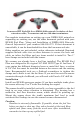
Some sonar or GPS display units may require a software upgrade to display NMEA 2000 data correctly. For free software upgrades or additional information on the LowranceNet NMEA 2000® network system, visit our web site, www.lowrance.com. The EP-60R consists of a red cable connector and the sensor module. The sensor module contains a turbine to measure fuel flow and electronics which convert flow data to the NMEA 2000 data format. The cable length from the connector to the smart module is 10 feet (3 meters).
LowranceNET Node Kit for a NMEA 2000 network. Includes a 2-foot extension cable, T connector and two 120-ohm terminators. For complete instructions on setting up a new NMEA 2000 network or expanding an existing one, see the other document packed with your EP-60R Fuel Flow, "Setup and Installation of NMEA 2000 Networks, General Information" part number 988-0154-173. If that document is unavailable, it can be downloaded free from the Lowrance web site.
Cut the fuel hose where you intend to install the EP-60R sensor. Slide a clamp over the hose coming from the tank, then push the hose onto the bottom (inlet) hose barb. Seat the hose flush against the sensor housing, then tighten the hose clamp. Attach the hose leading to the engine on the top (outlet) barb in the same way. To engine Flow direction From tank Push the fuel line onto the hose barb, then tighten the hose clamp. Orient the sensor vertically, with the flow arrow pointing up.
Connecting to a NMEA 2000 Network A NMEA 2000 network is a communications link between two or more devices that transfer NMEA 2000 information. LowranceNET is the NMEA 2000 networking system developed by Lowrance Electronics. A NMEA 2000 network functions like the phone wiring in a house. If, for example, you pick up a phone in the living room you will be able to hear the conversation someone is having on a phone in the bedroom.
Terminator at the end of the backbone (bus) Double T connector Cap for unused connector Backbone cable (to rest of bus) Cable from sensor or display unit NMEA 2000 network node located at the end of a NMEA 2000 backbone. NOTE: If you have a double T Connector on your network that is not attached to a device, you must cap the unused connector with a NMEA 2000 cap. This will protect the pin connectors from corrosion.
Use T-connector or double T connector to add device to bus (maintaining linear architecture) Backbone cable to rest of bus Existing network node Attach terminator at end of bus Devices connect to double T connector In this example, a new device is added to the NMEA 2000 bus by installing a T connector between a T connector and a terminator at the end of the backbone (network bus).
Notes 8
LMF-200: EP-60R Configuration & Calibration This section covers how to use the EP-60R Fuel Flow with a LMF-200 Multi-function gauge. NOTE: You will notice the LMF-200 does not have an Exit key. Menus will time out after a preset amount of time (3, 5, 10 or 15 seconds). The default setting is 5 seconds. Refer to your LMF-200 instruction manual for more information on the Timeout feature.
3. Select the tank you want to set up and press MENU, which will open the Tank Size window. 4. Use the UP and DOWN keys to input the number of gallons the tank will hold and press MENU. Repeat steps 3 and 4 for each additional tank. After all tanks have been set up, you will be directed to the main display. Boat Setup Reset If you want to access the Setup screen (Boat Setup) after an enginetank configuration has been chosen you will have to reset the configuration to default settings.
3. Select UNCFG FF and press MENU. The following message will appear: Hit Menu to Cfg Flow Sns. Press MENU and the Configuration options menu will appear. NOTE: If your unit is set to a single-engine configuration, the Configuration Options menu will not appear when you are configuring a fuel flow. The fuel flow will automatically be configured as Eng FFlow. 4. Select the desired option and press MENU. You will be directed to the Bus Devices list. Configure remaining fuel flows by following the steps above.
If all fuel flows configured (Configuration name unavailable): 1. Press MENU, use the UP and DOWN keys to select SYSTEM SETUP and press MENU. 2. Highlight B. DEVICES and press MENU. The Bus Devices list will appear. 3. Select the Port FFlow and press MENU. 4. Highlight UNSET ENGINE and press MENU. The following message will appear: Hit Menu to Unset Dev Name. 5. Press MENU and you will be taken back to the Bus Devices menu, where fuel flow (formerly Port FFlow) now will be displayed as UnCfg FFlow.
5. You will be taken back to the Bus Devices list, where the fuel flow you selected (formerly Port FFlow) will be listed as Stbd FFlow. If the newly configured fuel flow is not shown, refresh the Bus Devices list. Reset The Reset command in the Fuel Flow level menu will clear the sensor’s configuration and calibration settings. NOTE: After using the Reset command, you will have to re-enter your engine-tank configuration.
To customize Fuel Manager page: 1. With the Fuel Manager page displayed on the main display, press MENU, select CUSTOMIZE and press MENU. 2. Highlight USD (Fuel Used) and press MENU. If your unit is configured for more than one tank, the Select Tank menu will appear. (If your engine-tank configuration is set for one tank, you will be directed to the main display.) 3. Select the desired option and press MENU. You will be directed to the main display. To check fuel flow accuracy: 1.
9. The Recalibration (The Recal?) menu will appear with two options: Yes and No. Select YES and press MENU. NOTE: If you do not have the fuel remaining source set to Eng/FFlow, the recalibration message will not appear. 10. The Filled Quantity window will appear. Use the UP and DOWN keys to input the amount of fuel you added to the tank and press MENU. 11. Repeat these steps for each fuel flow you want to calibrate.
add fuel to a tank without completely filling it up, you must use the Partial Fill command. This will ensure the fuel information in the EP60R stays consistent with the amount of fuel actually in the tank. To use Partial Fill: 1. Press MENU, use the UP and DOWN keys to select SYSTEM SETUP and press MENU. Highlight FUEL MNGR and press MENU. 2. Highlight PART FILL and press MENU. The Select Tank menu will appear with up to three options.
To Reset Trip Fuel (Rst trip f) 1. Press MENU, use the UP and DOWN keys to select SYSTEM SETUP and press MENU. Highlight FUEL MNGR and press MENU. 2. Select RST TRIP F (Reset Trip Fuel) and press MENU. The Select Engine menu will appear with up to four options. Select the desired engine or All Engines and press MENU. (If you are using a single-engine configuration you will not see the Select Engine menu.) 3. The following message will appear: Hit Menu to Rst Trip F.
6. Use the UP and DOWN keys to input the desired percentage of tank capacity and press MENU. Let the menus time out to return to the main display. NOTE: To turn off a fuel warning, repeat Steps 1-4, then select OFF from the Level Percentage window mentioned in Step 5. Press MENU. Repeat these steps for each warning you want to turn off. Let the menus time out and you will be directed to the main display.
Autoscroll feature if you want the pages to automatically scroll across the screen. Refer to your LMF -200 manual for more information about Autoscroll. Adding a page: 1. Press MENU, use the UP and DOWN keys to select PAGES and press MENU, which will open the Pages menu with the following options: Add Page, Rem Page, Autoscroll and Set Pop-up. 2. Highlight ADD PAGE and press MENU. 3. Select Single Digital, Dual Digital or the Fuel Manager page and press MENU.
menu will appear, allowing you to display data from a single engine or show data from all engines. (If you select FUEL RANGE (RNG) or if your unit is configured for one engine, you will be taken back to the main display.) 5. Select the desired engine or, to display data from all engines, highlight Vessel and press MENU. You will be taken back to the main display, where the data you selected will be shown. Repeat these steps to customize the other data position. To customize Fuel Manager page: 1.
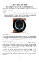
LMF-400: EP-60R Configuration & Calibration This section covers how to use the EP-60R Fuel Flow with a LMF-400 Multi-function gauge. LMF-400 Multi-function Digital gauge. Boat Setup If this is the first time you have turned on your LMF-400, you will have to complete Boat Setup before you will be able to configure or calibrate your fuel flow. If you have already completed Boat Setup, skip ahead to the segment covering EP-60R Fuel Flow Configuration. To execute Boat Setup: 1.
Boat Setup Reset If you want to access the Setup screen (Boat Setup) after an enginetank configuration has been chosen you will have to reset the configuration to default settings. To reset engine-tank configuration: 1. Press MENU, highlight SYSTEM SETUP and press ENTER. 2. Choose ENG/TANK CFG and press ENTER twice. The following message will appear: Press ENTER to reset Eng/Tnk Cfg. 3. Press MENU. The Setup Menu will appear with Boat Setup highlighted.
1. Press MENU, use the UP and DOWN keys to select SYSTEM SETUP and press ENTER. 2. Highlight BUS DEVICES and press ENTER. The Bus Devices list will appear. Bus Devices highlighted in the System Setup menu (left). Searching Bus Devices window (center) with Bus Devices list (right). 3. Select UNCFG F FLOW and press ENTER. The following message will appear: Press Enter to Configure Fuel Flow Snsr. 4. Press ENTER. If your unit is configured for more than one tank, the Select Engine menu will appear.
flow to free up its configuration name. If all three fuel flows are configured, which means there is no configuration name available, follow the first set of instructions. If the desired configuration name is available, follow the second set of instructions. Change Engine (active only with multiple-engine setting) The steps below show how to switch the configuration name of a fuel flow from Port engine to Starboard engine. If all fuel flows configured (Configuration name unavailable): 1.
EP-60R Fuel Flow Calibration The factory calibration settings for the EP-60R Fuel Flow should be within 3 percent, so calibration will not be necessary in most cases. NOTE: The Fuel Remaining Source must be set to fuel flow for the unit to correctly display fuel level information. Follow the instructions below to ensure fuel flow (Eng/FFlow) has been selected as the Fuel Remaining Source. It is set to fluid level by default.
2. Press MENU, use the UP and DOWN keys to select SYSTEM SETUP and press ENTER. 3. Highlight FUEL SETUP and press ENTER. 4. Select REFILL TANK and press ENTER. If your unit is configured for more than one tank, the Select Tank menu will open. 5. Select the tank you refilled and press ENTER. A Recalibration window (ReCalibrate?) will appear with two options: Yes and No. Select NO and press ENTER. The following message will appear: Press Enter after refilling the fuel tank. Press ENTER. 6.
2. Highlight BUS DEVICES and press ENTER. Highlight the fuel flow you want to reset and press ENTER. 3. Select RESET CAL from the fuel flow menu and press ENTER. The following message will appear: Press Enter to reset the Calibration. 4. Press ENTER to set calibration back to default settings. To recalibrate the fuel flow, follow the fuel flow calibration steps in this section.
NOTE: When using the Partial Fill command, you will only be able to input into the gauge, an amount of fuel less or equal to the fuel used figure. The unit will not allow you to enter a fuel amount greater than the fuel used figure. 4. Use the UP and DOWN keys to input the amount of fuel added to the tank and press ENTER. You will be taken back to the main display.
To reset seasonal fuel: 1. Press MENU, select SYSTEM SETUP and press ENTER. 2. Highlight FUEL SETUP and press ENTER. 3. Select RESET SEASONAL and press ENTER. The Select Engine menu will appear with up to four options. (If you have one engine, the reset seasonal fuel message (Step 4) will appear.) 4. Select the desired engine or All Engines and press ENTER. The following message will appear: Press Enter to reset Seasonal Fuel. 5. Press ENTER to reset seasonal fuel.
To set an Engine Warning (Alarm): 1. Press MENU, use the UP and DOWN keys to highlight SYSTEM SETUP, and press ENTER. 2. Highlight ENGINE WARNINGS and press ENTER. The Engine Warnings menu will appear with up to five options, including Off and All Engines. The default setting is All Engines. (If you have a single-engine configuration, the only options on the Engine Warning menu will be On and Off.) 3. Choose the desired option and press ENTER. You will be taken back to the main display.
To customize Single Digital page: 1. After the Single Digital page has been added to the page screen rotation, use the ENTER and EXIT keys to display it on the main screen. 2. Press MENU, use the UP and DOWN keys to select CUSTOMIZE and press ENTER. The data menu will appear. 3. Highlight Fuel Flow, Fuel Range, Fuel Used, Trip Fuel Used or Seasonal Fuel and press ENTER. A menu will appear, allowing you to display data from a single engine or from all engines.
data from a single engine or from all engines on the vessel. (If you select FUEL RANGE or if your unit is configured for one engine, you will be taken back to the Position menu.) 5. Select the desired engine or, to display data from all engines, highlight Vessel and press ENTER. You will be taken back to the Position menu. To display data in another data box, repeat Steps 3-5. 6. Press EXIT twice to return to the main display. To customize Fuel Manager page: 1.
Display Unit: EP-60R Configuration & Calibration All NMEA 2000 capable Lowrance sonar and sonar/GPS combo display units can be used to configure and calibrate your EP-60R Fuel Flow sensor on a NMEA 2000 network. The LMS-525cDF is one of many Lowrance display units that may be used to configure an EP-60R Fuel Flow sensor. NOTE: Your unit may have NMEA 2000 menu or a Networking menu, depending on your display unit's software version. Both menus allow you to perform the same NMEA 2000 related functions.
Bus Setup highlighted on the NMEA 2000 menu (left). Bus Setup selected on Networking menu (right). The Engine-Tank Configuration and Tank Select menus as well as the Tank Size dialog box are located on the bottom half of the Bus Configuration menu. The Set Configuration button — positioned next to the engine-tank configuration menu — allows you to finalize a selected configuration. Bus Configuration menu (left). NMEA Diagnostics page (center). Ethernet Diagnostics (right).
Setting Engine-Tank Configuration: 1. Press MENU twice, highlight NMEA 2000 or NETWORKING and press ENTER. 2. The NMEA 2000 menu will appear with five options: Bus Setup, Fuel Management, NMEA 2000 Alarms, Waypoint Sharing and Backlight Synchronization. Choose BUS SETUP and press ENTER. 3.
menu. To configure or calibrate most devices, you will select it on the NMEA 2000 Devices list and press ENTER. This will open its Device Configuration menu. Bus Configuration menu with five items displayed on the NMEA 2000 Devices list. Engine-Tank Configuration and Tank Select menus are at the bottom of the screen. Device Configuration Menu When a device is selected from the network devices list on the Bus Configuration menu, its Device Configuration menu will appear.
EP-60R Fuel Flow Configuration When configuring your fuel flow, you will open its Device Configuration menu where you can access the Location and Advanced Options menu. You can also change your fuel flow's device name. Device Name You can change how your fuel flow will be displayed on your unit's NMEA 2000 Devices list by inputting a customized device name in the Device Name dialog box. NOTE: Changing the Device Name only will affect the way the EP-60R is shown on your display unit.
5. Highlight the device and press ENTER. The Device Configuration menu will open. The device name will be reset to its default setting. Press EXIT repeatedly to return to the main display. Location The Location menu allows you to select a configuration name that matches the location of the engine connected to your fuel flow sensor. To change fuel flow location: 1. Press MENU twice, select NMEA 2000 or NETWORKING and press ENTER.
Fuel Management highlighted on Networking menu (left). Fuel Management menu (right). Fuel Management Menu The Fuel Management menu gives you access to the following options: Tank Location, Fuel Added, Add Fuel, Fill Tank, Engine Select, Reset Calibration, Reset Trip and Reset Seasonal. The menu is divided into two parts: Tank Operations and Engine Operations. You will calibrate your fuel flow from Tank Operations section of the Fuel Management menu.
If you filled up the tank: A. Press the FILL TANK button and press ENTER. The following message will appear: Are you sure you wish to Fill Tank? Press ENTER. Another message will appear: Do you wish to re-calibrate the device? Highlight NO and press ENTER. If you did not fill up the tank: B. Highlight FUEL ADDED and press ENTER to access the FUEL ADDED dialog box. Use ↑ ↓ , ← → to input the amount of fuel added to the tank and press ENTER. Select the ADD FUEL button and press ENTER.
4. Highlight FILL TANK and press ENTER. The following confirmation message will appear: Are you sure you wish to Fill Tank? NOTE: You must use the unit’s Fill Tank command when filling your fuel tank to keep the fuel flow updated with correct information on the amount of fuel in the tank. 5. Select YES and press ENTER. The following confirmation message will appear: Do you wish to re-calibrate the device? 6. Highlight NO and press ENTER. 7.
To Reset Calibration: Choosing the Reset Calibration command will switch fuel flow calibration settings back to factory defaults. 1. Press MENU twice, select NMEA 2000 or NETWORKING and press ENTER. 2. Highlight FUEL MANAGEMENT and press ENTER. 3. Highlight to ENGINE SELECT and press ENTER. Select the desired engine and press ENTER. 4. Highlight RESET CALIBRATION and press ENTER. The following confirmation message will appear: Are you sure you wish to Reset Calibration? Select YES and press ENTER.
Displaying data from fuel flow The Overlay Data function will be used to show EP-60R Fuel Flow data on your unit's main display. To add overlay data from the EP-60R: 1. Press MENU, highlight OVERLAY DATA and press ENTER. 2. Select (PRESS ENT TO ADD…) and press ENTER. 3. Highlight NMEA 2000 and press ENTER. A list of devices on the network will appear. 4. Select the desired fuel flow and press ENTER. Fuel Rate, Fuel Used, Trip Fuel Used and Seasonal Fuel Used categories will appear. 5.
Alarm Status Tab The Alarm Status tab is the second tab at the top of the NMEA 2000 Alarms page. When an alarm has been set for a device, the alarm and its current status will be shown on the Alarm Status window. To view Alarm Status: 1. Press MENU twice, select NMEA 2000 or NETWORKING and press ENTER. 2. Select NMEA 2000 ALARMS and press ENTER. 3. Highlight the Alarm Status tab. 4. Press EXIT repeatedly to return to the main display.
Notes 45
Notes 46
LOWRANCE ELECTRONICS FULL ONE-YEAR WARRANTY "We," "our," or "us" refers to LOWRANCE ELECTRONICS, INC., the manufacturer of this product. "You" or "your" refers to the first person who purchases this product as a consumer item for personal, family or household use. We warrant this product against defects or malfunctions in materials and workmanship, and against failure to conform to this product's written specifications, all for one (1) year from the date of original purchase by you.
How to Obtain Service… …in the USA: Contact the Factory Customer Service Department. Call toll-free: For Lowrance: 800-324-1356. For Eagle: 800-324-1354 8 a.m. to 5 p.m. Central Standard Time, M-F Lowrance Electronics and Eagle Electronics may find it necessary to change or end their shipping policies, regulations and special offers at any time. They reserve the right to do so without notice. …in Canada: Contact the Factory Customer Service Department.